A stereo jack can contain switches as well as contacts that touch the plug. Build a direct-current (DC) fixture for the Same Sky SJ1-3525N. Give the empty jack and the two plug contacts different voltage signatures. A digital multimeter (DMM) then shows which path is present without putting a phone, speaker or amplifier on the bench.
Identify the terminals before wiring
Use the exact Same Sky SJ1-3525N, a right-angle through-hole 3.5 mm stereo jack with two internal switches. The manufacturer specifies 12 V DC and 1 A and lists −25 to 85 °C operation. These are connector specifications, not recommended conditions for this fixture. The source here is only 3.30 V, with 5 mA programmed as the supply current setting. A normal contact is the spring connection present in the absence of a plug. A fully seated tip–ring–sleeve (TRS) plug has a conductor at its nose, an insulated middle band and the long rear sleeve. Tip and ring each lift their separate normal contact. The sleeve supplies a common reference.
Use the data sheet’s page 2 top-view footprint and pin assignment for the exact model. Pin 1 is sleeve, 2 tip, 3 ring, 10 tip normal, and 11 ring normal. The schematic switch callouts 4 and 5 describe the switch functions; the printed-circuit-board (PCB) terminals to wire are 10 and 11. Do not mirror the top view when marking the pins. With all power disconnected, use the DMM continuity function to confirm 2–10 and 3–11 close without a plug and open when it is fully seated. Check that tip, ring and sleeve are separate on the unwired plug before soldering a cable. Use a REAN NYS231 3.5 mm stereo plug with three insulated conductors and mark both ends from the contact bands using continuity. Wire colors are not a pinout.
Give the two paths different voltage signatures
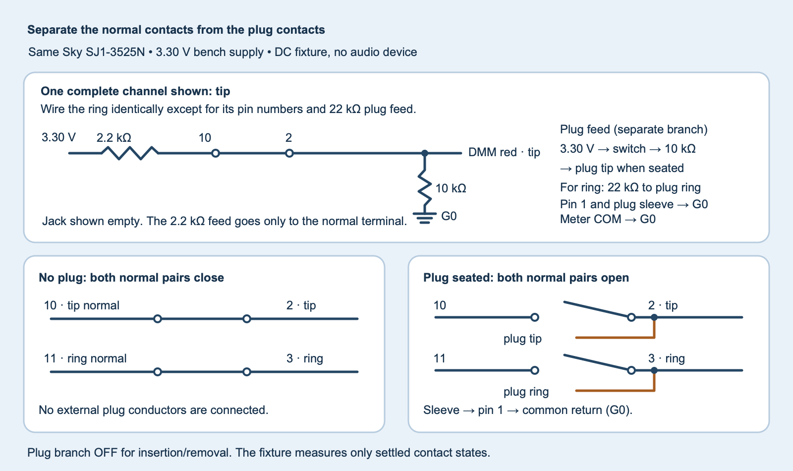
fixture.svg).- With a SIGLENT SPD3303X channel 1 set to 3.30 V and a 5 mA programmed current setting, switch its output off. Use the channel in independent mode. Connect its negative terminal, jack pin 1, the plug sleeve wire and Fluke 115 black COM lead to the same common return G0. COM means common, the meter’s voltage reference.
- Use 1%, ¼ W metal-film resistors throughout. Connect an independent 2.2 kΩ from the supply rail to each normal pin (10 and 11). Connect a separate 10 kΩ from pin 2 to G0 and another from pin 3 to G0. Leave pins 2 and 3 separate. The red meter lead reads these pins one at a time.
- Install a single-pole single-throw switch between 3.30 V and the two plug-feed resistors. Beyond the switch, connect one 10 kΩ to the plug tip wire and one 22 kΩ to the plug ring wire. No audio device, adapter or earphone connects to this fixture. With the switch open, the plug branch cannot drive either contact.
When the empty jack closes a normal pair, 2.2 kΩ on top and 10 kΩ below give a voltage-divider ratio of 10 ÷ 12.2 ≈ 0.820, or 2.70 V at 3.30 V. With the plug seated and its feed off, the normal path opens and the 10 kΩ pulldown sets each node near zero. With plug feed on, the two ratios become 10 ÷ 20 = 0.500 (tip) and 10 ÷ 32 = 0.313 (ring). A 10 MΩ voltmeter in parallel with a 10 kΩ pulldown changes that pulldown by less than 0.1%. Even if both nodes were shorted during motion while all feeds were energized, the four feed resistors would limit the ideal current at 3.40 V to under 3.7 mA using their 1% low limits. Keep the plug feed off for insertion and removal regardless. The test measures settled states and says nothing about transient shorts, contact order or audio pops.
Record four settled states
- Start with the plug out and its feed switch off. Turn on the bench rail. Put the Fluke 115 on the fixed 6.000 V DC range with the red lead in the voltage jack. Record rail, tip pin 2 and ring pin 3 in the
emptyrow of the blank worksheet (ZIP:observations-blank.csv). - Seat the plug fully with its bias switch still off. Record all three voltages in
inserted_bias_off. The drop from the empty signature is evidence that the normal paths opened with no feed through the plug. - With the plug stationary, close the bias switch and record
inserted_bias_on. Distinct tip and ring ratios identify the two active plug wires. If the two signatures are reversed, open the switch and trace both wires with the supply off. - Open the plug-feed switch and remove the plug. Record
empty_repeatto check that both normal contacts reclosed. Switch off the bench output before moving any fixture wire.
In the worksheet, enter only measured volts. The analyzer uses each row’s measured rail and bounds each meter indication by 0.5% of reading plus two 1 mV counts under the Fluke 115 specification. It compares the complete ratio interval with the fixture bands 0–0.05, 0.30–0.34, 0.47–0.53 and 0.79–0.85. These bands are chosen to separate the 1% resistor dividers and do not certify the manufacturer’s milliohm contact rating. The meter allowance assumes the specified range, temperature, humidity and calibration conditions. An interval touching two decisions or any value in the gaps is unresolved; check the actual wiring and measurements rather than forcing a label.
Challenge: Both channels are near zero with plug feed off. What do you know?
The empty-path voltage is gone, so the normal feeds no longer hold the measured pins high. You cannot yet tell whether the plug wires are connected correctly. Close the bias switch with the plug seated and look for the distinct 0.500 and 0.313 ratios.
Run the complete worksheet analyzer
Download the experiment files (ZIP: experiment-tests-v1.zip) and run python3 jack_states.py observations.csv. Exit 2 means a worksheet cannot be read; exit 3 reports unexpected or unresolved states. The included tests use constructed input values. No hardware results are supplied.
Complete Python worksheet analyzer
"""Compare two switched audio-jack contacts in a low-voltage test fixture."""
import argparse
import csv
import json
import math
from pathlib import Path
import sys

HEADER = ("state", "rail_v", "tip_v", "ring_v")
STATES = ("empty", "inserted_bias_off", "inserted_bias_on", "empty_repeat")
EXPECTED = (("normal", "normal"), ("low", "low"), ("plug_tip", "plug_ring"), ("normal", "normal"))
EPS = 1e-12
BANDS = {"low": (0.00, .05), "plug_ring": (.30, .34), "plug_tip": (.47, .53), "normal": (.79, .85)}


def interval(reading):
    allowance = abs(reading) * .005 + .002
    return reading - allowance, reading + allowance


def classify(voltage, rail):
    v0, v1 = interval(voltage)
    r0, r1 = interval(rail)
    bounds = (max(0, v0) / r1, v1 / r0)
    labels = [name for name, (a, b) in BANDS.items() if a - EPS <= bounds[0] <= bounds[1] <= b + EPS]
    return {"ratio": voltage / rail, "meter_screen": bounds, "label": labels[0] if labels else "unresolved"}


def read_rows(stream):
    csv_rows = csv.reader(stream, strict=True)
    if tuple(next(csv_rows, ())) != HEADER:
        raise ValueError("use the exact worksheet header")
    for state in STATES:
        row = next(csv_rows, ())
        if len(row) != 4 or row[0] != state:
            raise ValueError(f"expected row {state}")
        try:
            rail, tip, ring = map(float, row[1:])
        except ValueError:
            raise ValueError(f"{state}: enter three voltages") from None
        if not all(map(math.isfinite, (rail, tip, ring))):
            raise ValueError(f"{state}: voltages must be finite")
        if not 3.20 <= rail <= 3.40 or not all(-.002 <= x <= rail + .025 for x in (tip, ring)):
            raise ValueError(f"{state}: check fixture rail and probe positions")
        yield state, rail, max(0, tip), max(0, ring)
    if next(csv_rows, None) is not None:
        raise ValueError("unexpected additional rows")


def analyze(stream):
    observed = []
    for (state, rail, tip, ring), expected in zip(list(read_rows(stream)), EXPECTED):
        nodes = [classify(tip, rail), classify(ring, rail)]
        labels = tuple(n["label"] for n in nodes)
        observed.append({"state": state, "rail_v": rail, "tip": nodes[0], "ring": nodes[1],
                         "expected": expected, "matches": labels == expected})
    wired_swap = (observed[2]["tip"]["label"], observed[2]["ring"]["label"]) == ("plug_ring", "plug_tip")
    return {"all_stable_states_match": all(row["matches"] for row in observed),
            "plug_signature_swapped": wired_swap, "observed": observed}


def main():
    cli = argparse.ArgumentParser(description=__doc__)
    cli.add_argument("worksheet", type=Path)
    args = cli.parse_args()
    try:
        if args.worksheet.stat().st_size > 4096:
            raise ValueError("one four-row worksheet per run")
        with args.worksheet.open(encoding="utf-8-sig", newline="") as stream:
            report = analyze(stream)
    except (OSError, ValueError, csv.Error) as exc:
        print(f"Worksheet rejected: {exc}", file=sys.stderr)
        return 2
    print(json.dumps(report, indent=2, allow_nan=False))
    return 0 if report["all_stable_states_match"] else 3


if __name__ == "__main__":
    sys.exit(main())
The connector pitch experiment shows another reason to identify a connector’s exact mechanical variant.
Primary references
Download the complete reader files (ZIP) for the original editable drawing, PNG, worksheet and code in sj1-switched-jack-contact-map. The full main program is also included above.