Turn a small direct-current (DC) voltage into pulses whose high time changes while the time from one rising edge to the next stays nearly fixed. That is pulse-width modulation (PWM). The Analog Devices LTC6992-1 has separate controls for the oscillator and the pulse width. Sweep its control voltage and check those two behaviors independently. Then look for something an automatic frequency display cannot describe: an output that stays at a rail.
Wire the exact oscillator
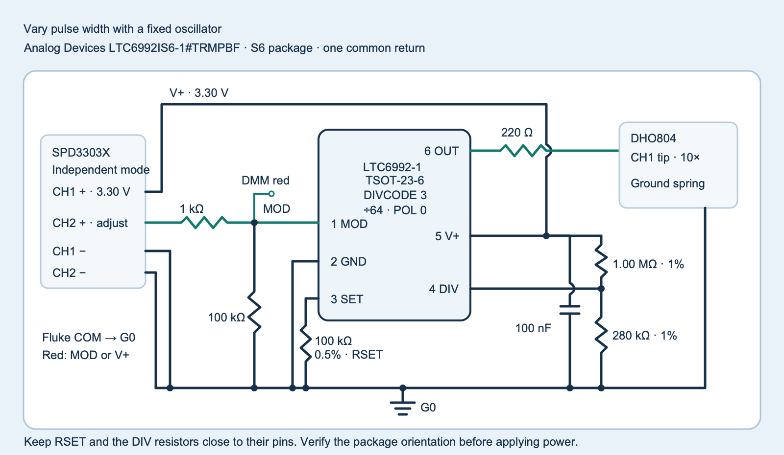
Use an Analog Devices LTC6992IS6-1#TRMPBF, marked LTDXB, in the thin, six-lead small-outline transistor package (TSOT-23-6, S6). The I-grade specification covers −40 to 85 °C. The chip operates from 2.25 to 5.5 V and the fixture uses 3.30 V. The 6 V absolute maximum supply rating is a stress limit. Keep every signal within the applied supply rails here. The −1 version can reach a settled low or high output. The −2 version deliberately keeps pulsing at both ends of its control range, so order the exact suffix. Check pin numbering against the data sheet’s S6 top view and continuity-check the short adapter traces before power-up.
Download the editable diagram (ZIP: fixture.svg) or get the bench files and host tests (ZIP: experiment-tests-v1.zip).
| Pin | Bench connection |
|---|---|
| 1 MOD | Adjustable channel 2 through 1 kΩ. Fit 100 kΩ to G0 and measure here. |
| 2 GND | Common return G0, with short paths from the resistors and bypass capacitor. |
| 3 SET | 100 kΩ to G0, 0.5% or better and at most 50 ppm/°C. Keep the node compact and free of a probe or added capacitor. |
| 4 DIV | 1.00 MΩ to V+ and 280 kΩ to G0, both 1%. Keep this node away from fast output traces. |
| 5 V+ | Channel 1 at 3.30 V with a 100 nF ceramic capacitor placed directly between pins 5 and 2. |
| 6 OUT | 220 Ω in series to the probe tip, with no additional load. |
Use the two adjustable outputs of a SIGLENT SPD3303X in independent mode. Tie their negative terminals, the Fluke 115 digital multimeter (DMM) COM terminal and the RIGOL DHO804 scope’s probe ground spring to G0. Keep protective earth connected. Set both outputs off before wiring. Program channel 1 for 3.30 V with a 20 mA current setting and channel 2 for 0 V with a 20 mA current setting. Turn on V+ first. Increase channel 2 only while V+ is present. For shutdown, return channel 2 to 0 V, disable it, then disable V+. Adjust channel 2 by the DMM reading at pin 1, since the 1 kΩ series and 100 kΩ pull-down change the supply setting slightly. Keep MOD between 0 and 1.01 V in the fixture. Leave the 100 kΩ in place if channel 2 is off.
Separate repetition rate and high time
The DIV divider ratio is 280 ÷ (1000 + 280) = 0.21875. The data sheet’s Table 1 maps it to divider code 3, division by 64 and noninverting polarity (POL = 0). The resistor combination has a nominal driving impedance of 218.75 kΩ, within the 500 kΩ limit. With 1% resistors the ratio lies about 0.2154–0.2222 before input loading. A ±10 nA DIV input current contributes about ±2.2 mV nominal, well inside the code’s ±0.015 ratio allowance at the bench rail. Leave DIV fixed during the experiment.
With a SET resistor to G0, oscillator frequency follows the resistor value. Each complete cycle runs from one rising edge to the next. The nominal period here is 128 µs.
fOUT = (1 MHz × 50 kΩ) / (64 × 100 kΩ) = 7812.5 Hz
Duty is the fraction of a cycle for which OUT is high. The control input sets that fraction. In the linear region, with the SET pin’s nominal internal reference of 1.00 V, the model is:
D ≈ (VMOD − 0.10 V) / 0.80 Vhigh time ≈ D × 128 µs
At 0.25, 0.50 and 0.75 V the model predicts 18.75%, 50% and 81.25% duty, or 24, 64 and 104 µs high. Compare those with your own measurements. The SET reference can be 0.97–1.03 V. Treat the equation with 1.00 V as a nominal model and allow for duty error and the capture method. With a 0.5% SET resistor, resistor tolerance alone moves the calculated frequency by about ±0.5%. The electrical table also lists a ±2.4% frequency limit over temperature under its test conditions. The analyzer uses a separate fixture comparison screen.
At the low and high ends the −1 variant can stop producing edges at OUT. The data-sheet bounds give a conservative low control threshold of 0.064 × 0.97 V ≈ 62 mV and high threshold of 0.936 × 1.03 V ≈ 964 mV. The worksheet’s 0.050 and 1.000 V targets leave margin even with the Fluke 115’s 6.000 V range allowance. Use that fixed range with 1 mV counts and ±(0.5% of reading plus two counts), under the manual’s 18–28 °C and 0–90% relative humidity conditions within one year of calibration.
Capture three interior points, two endpoints and a repeat
- Use a compensated RIGOL PVP2350 10× probe with the matching scope attenuation, DC coupling and the scope’s high-impedance input. Use a short ground spring. Set the same vertical range for every capture and check that G0 and 3.30 V fit without clipping. Keep SET and DIV unprobed.
- At each point, trim the control to within ±5 mV of the target as measured at MOD. Record V+ and MOD in a copy of the six-row worksheet (ZIP:
sweep-blank.csv). Keep V+ between 3.25 and 3.35 V. Capture only after the setting is stable. Wait at least 0.1 s after each change and keep the first transition after startup or adjustment outside the record. - Keep at least 1.5 ms of settled waveform and sample spacing at most 2 µs. Start near 200 µs/div with a manageable memory depth such as 10 kpts, then confirm actual span and spacing. At interior settings, use edge triggering and stop after a stable acquisition. For endpoints use Auto or force an acquisition. A Normal trigger may simply leave the old pulsing display in memory.
- Export the stopped acquisition as Save Wave → Memory → CSV. Keep the original file. In a copy, retain the actual sample times in seconds and CH1 volts with the exact two-column header (ZIP:
trace-blank.csv). Retain native samples and keep each file under 4 MB. Name the fileslow.csv,quarter.csv,middle.csv,three_quarters.csv,high.csvandmiddle_repeat.csv, in that sweep order. The repeated 0.50 V reading checks return after visiting both extremes. - For an endpoint, also inspect a fresh wider capture and a faster acquisition if narrow pulses could matter. A finite record cannot exclude pulses outside the window or between samples. If the display shows intermittent activity, save it separately and leave the static conclusion unresolved.
Interpret the result without forcing a frequency
The script finds midpoint crossings by interpolating between saved samples. It needs eight complete rising–falling–rising cycles and at least two captured points in each low and high region per cycle, at 20% or below and 80% or above the measured rail. It reports median duty and the reciprocal of median period. It checks each interior frequency within 4% of nominal, duty within nine percentage points of the model, with a period spread of at most 6% of the median and duty spread of at most six percentage points. Across the four interior captures it checks at most 3% frequency span, at least 12 percentage points between neighboring planned duty levels, and a 4-point middle-repeat limit.
A static capture has every sample within 0.15 V of the relevant rail. The report leaves both frequency and measured duty empty, since no cycle was captured. The theoretical duty endpoints describe the expected logic state. If the scope still reports a number, check for stale acquisition, incorrect triggering, ringing or a different chip suffix. A failing comparison describes this capture and fixture. It does not diagnose a failed component.
Challenge: Can you use a steady high OUT to calculate the oscillator period?
No cycle boundary appears in a steady high capture. Return MOD to 0.50 V, wait for settling, and use the spacing between rising edges. With the same SET and DIV networks the nominal value is 128 µs.
Run the complete capture analyzer
Place the six captures beside the filled worksheet. Run python3 pwm_sweep.py sweep-filled.csv. Exit 0 means all comparison screens pass, exit 3 reports a valid capture set with an unresolved comparison, and exit 2 reports a rejected input or missing file. The supplied tests use constructed waveforms. The worksheets contain no physical bench measurements.
Complete Python capture analyzer
"""Check six settled LTC6992-1 captures from the fixed-divider bench fixture."""

import argparse
import csv
import json
import math
from pathlib import Path
from statistics import median
import sys

STEPS = (
    ("low", .05), ("quarter", .25), ("middle", .50),
    ("three_quarters", .75), ("high", 1.00), ("middle_repeat", .50),
)
TRACE_HEADER = ("time_s", "out_v")
SWEEP_HEADER = ("step", "vplus_v", "mod_v")
MAX_DT = 2e-6
MIN_WINDOW = 1.5e-3
F_NOMINAL = 7812.5
EPS = 1e-12


def finite(value):
    number = float(value)
    if not math.isfinite(number):
        raise ValueError("expected a finite number")
    return number


def meter_error(value):
    return .005 * abs(value) + .002


def read_trace(path, rail):
    if path.stat().st_size > 4_000_000:
        raise ValueError("capture exceeds 4 MB")
    trace = []
    with path.open(encoding="utf-8-sig", newline="") as stream:
        reader = csv.reader(stream, strict=True)
        if tuple(next(reader, ())) != TRACE_HEADER:
            raise ValueError("use exact capture headings time_s,out_v")
        for row in reader:
            if len(row) != 2:
                raise ValueError(f"line {reader.line_num}: expected time and OUT voltage")
            time, voltage = map(finite, row)
            if abs(time) > 1 or not -.25 <= voltage <= rail + .25:
                raise ValueError(f"line {reader.line_num}: time or voltage outside fixture bounds")
            if trace and not 0 < time - trace[-1][0] <= MAX_DT + EPS:
                raise ValueError(f"line {reader.line_num}: sample spacing must be positive and ≤2 µs")
            trace.append((time, voltage))
    if len(trace) < 2 or trace[-1][0] - trace[0][0] < MIN_WINDOW - EPS:
        raise ValueError("capture must cover at least 1.5 ms")
    return trace


def classify_trace(trace, rail):
    voltages = [value for _, value in trace]
    low = .20 * rail
    high = .80 * rail
    if max(map(abs, voltages)) <= .15 + EPS:
        return {"shape": "static_low", "complete_cycles": 0, "frequency_hz": None, "duty": None}
    if max(abs(value - rail) for value in voltages) <= .15 + EPS:
        return {"shape": "static_high", "complete_cycles": 0, "frequency_hz": None, "duty": None}

    midpoint = rail / 2
    edges = []
    for i, ((t0, y0), (t1, y1)) in enumerate(zip(trace, trace[1:])):
        if (y0 < midpoint) == (y1 < midpoint):
            continue
        crossing = t0 + (midpoint - y0) * (t1 - t0) / (y1 - y0)
        edges.append((crossing, y1 > y0, i))

    duties = []
    periods = []
    complete = 0
    for first, second, third in zip(edges, edges[1:], edges[2:]):
        start, rising, start_i = first
        fall, _, fall_i = second
        end, _, end_i = third
        if not rising:
            continue
        complete += 1
        high_count = sum(y >= high for y in voltages[start_i + 1:fall_i + 1])
        low_count = sum(y <= low for y in voltages[fall_i + 1:end_i + 1])
        if high_count < 2 or low_count < 2:
            continue
        period = end - start
        periods.append(period)
        duties.append((fall - start) / period)
    if len(periods) < 8 or len(periods) != complete:
        return {"shape": "unresolved", "complete_cycles": len(periods), "frequency_hz": None, "duty": None}
    frequency = 1 / median(periods)
    duty = median(duties)
    return {
        "shape": "pwm", "complete_cycles": len(periods),
        "frequency_hz": frequency, "duty": duty,
        "period_spread_fraction": (max(periods) - min(periods)) / median(periods),
        "duty_spread": max(duties) - min(duties),
    }


def read_conditions(path):
    if path.stat().st_size > 4096:
        raise ValueError("sweep worksheet exceeds 4 KiB")
    with path.open(encoding="utf-8-sig", newline="") as stream:
        reader = csv.reader(stream, strict=True)
        if tuple(next(reader, ())) != SWEEP_HEADER:
            raise ValueError("use exact sweep headings step,vplus_v,mod_v")
        rows = []
        for step, target in STEPS:
            row = next(reader, ())
            if len(row) != 3 or row[0] != step:
                raise ValueError(f"expected row {step}")
            rail, mod = map(finite, row[1:])
            if not 3.25 <= rail <= 3.35:
                raise ValueError(f"{step}: measured rail must be 3.25–3.35 V")
            if abs(mod - target) > .005 + EPS:
                raise ValueError(f"{step}: measured MOD must be within 5 mV of {target:.2f} V")
            rows.append((step, rail, mod))
        if next(reader, None) is not None:
            raise ValueError("unexpected additional sweep row")
    return rows


def analyze(worksheet):
    steps = {}
    for step, rail, mod in read_conditions(worksheet):
        try:
            capture = read_trace(worksheet.parent / (step + ".csv"), rail)
        except (OSError, csv.Error, ValueError) as error:
            raise ValueError(f"{step}: {error}") from None
        report = classify_trace(capture, rail)
        vm_error = meter_error(mod)
        report.update(mod_v=mod, vplus_v=rail, capture_span_s=capture[-1][0] - capture[0][0])
        if step == "low":
            report["step_screen_pass"] = report["shape"] == "static_low" and mod + vm_error < .064 * .97
        elif step == "high":
            report["step_screen_pass"] = report["shape"] == "static_high" and mod - vm_error > .936 * 1.03
        else:
            predicted = (mod - .10) / .80
            report["nominal_duty"] = predicted
            report["step_screen_pass"] = (
                report["shape"] == "pwm"
                and abs(report["frequency_hz"] / F_NOMINAL - 1) <= .04 + EPS
                and abs(report["duty"] - predicted) <= .09 + EPS
                and report["period_spread_fraction"] <= .06 + EPS
                and report["duty_spread"] <= .06 + EPS
            )
        steps[step] = report

    interior = [steps[key] for key in ("quarter", "middle", "three_quarters", "middle_repeat")]
    all_pwm = all(row["shape"] == "pwm" for row in interior)
    frequency_span = duty_order = center_repeat = None
    if all_pwm:
        frequencies = [row["frequency_hz"] for row in interior]
        duties = [row["duty"] for row in interior]
        frequency_span = (max(frequencies) - min(frequencies)) / median(frequencies)
        duty_order = duties[1] - duties[0] >= .12 - EPS and duties[2] - duties[1] >= .12 - EPS
        center_repeat = abs(duties[1] - duties[3]) <= .04 + EPS
    checks = {
        "every_step_screen_passes": all(row["step_screen_pass"] for row in steps.values()),
        "interior_frequency_span_at_most_3_percent": frequency_span is not None and frequency_span <= .03 + EPS,
        "interior_duty_increases_by_at_least_12_points": duty_order is True,
        "middle_duty_repeats_within_4_points": center_repeat is True,
    }
    return {"all_checks_pass": all(checks.values()), "checks": checks, "steps": steps,
            "interior_frequency_span_fraction": frequency_span, "nominal_frequency_hz": F_NOMINAL}


def main():
    parser = argparse.ArgumentParser(description=__doc__)
    parser.add_argument("worksheet", type=Path)
    args = parser.parse_args()
    try:
        report = analyze(args.worksheet)
    except (OSError, csv.Error, ValueError) as error:
        print(f"Sweep rejected: {error}", file=sys.stderr)
        return 2
    print(json.dumps(report, indent=2, allow_nan=False))
    return 0 if report["all_checks_pass"] else 3


if __name__ == "__main__":
    raise SystemExit(main())
Primary references and related experiment
- Analog Devices, LTC6992 family data sheet, Rev. D and LTC6992 product page and orderable options.
- RIGOL, DHO800 user guide and PVP2350 probe guide.
- SIGLENT SPD3303X independent outputs and Fluke 115 DC range and accuracy.
- Compare with the TLC555 one-shot experiment, which measures one triggered pulse.
Download the complete reader files (ZIP) for the original editable drawing, PNG, worksheet and code in ltc6992-fixed-frequency-duty-sweep. The full main program is also included above.