Send a steady 2.25 V signal through one channel of a Nexperia 74HC4066 and change the load from 10 kΩ to 2.2 kΩ. The switch stays enabled for both runs. Measure both switch terminals and the voltage directly between them to see how load current affects the signal. At the end, disable the channel and observe how the load gives the output a defined return to ground.
An analog switch passes a continuously varying voltage when its control input enables it. This part has four independent switches. Each is a single-pole, single-throw switch (SPST), meaning one controllable connection between two terminals. The connection is bilateral, so either signal terminal can be assigned as the input in this voltage range. Current encounters a finite on-resistance while the path conducts. A voltage meter can reveal the drop directly if the load draws enough current.
This is a proposed low-voltage bench experiment. The wiring and arithmetic are documented for you to try. All example readings are constructed. The worksheet contains no bench results.
Choose the exact part and measuring tools
- One Nexperia 74HC4066D,653 (ordering code 933714420653). Its 14-lead small-outline integrated circuit package is SO14, outline SOT108-1. Use a plain SO14-to-2.54 mm adapter that exposes the original pins individually. Align the pin-1 marks on the chip and adapter. Confirm each header label by continuity from the corresponding pad before powering anything.
- Two adjustable, current-limited direct-current outputs (DC). Use isolated outputs that the supply manual permits you to join at their negative terminals. Set S1 to 4.50 V with a 10 mA limit and S2 to 2.25 V with a 2 mA limit. Set and measure both voltages before attaching the fixture. The limits apply to this bench setup.
- One 100 nF ceramic capacitor, one 2.2 kΩ and one 10 kΩ resistor, both 1% and ¼ W, a three-pin jumper header, a removable shunt, and short breadboard wires. A shunt is a removable link that joins two header pins. Here it selects the state of the enable input.
- One battery-powered Fluke 87V MAX digital multimeter, with leads in COM (common) and the voltage/resistance jack. A second matching meter is optional for simultaneous readings. The meter measures voltage across a component without breaking the path.
Use the HC type shown. The designation identifies high-speed complementary metal-oxide-semiconductor (CMOS) logic in this family. Nexperia specifies its recommended supply range as 2.0–10.0 V. Both signal terminals must stay between ground and the actual supply voltage. At 4.5 V the data sheet specifies that a control input is high at 3.15 V or higher and low at 1.35 V or lower. Here the shunt connects enable to one rail or the other. The separate 74HCT4066 family has different enable thresholds and supply conditions. The diagram and calculations are for the specified HC orderable.
Wire one channel and define the unused terminals
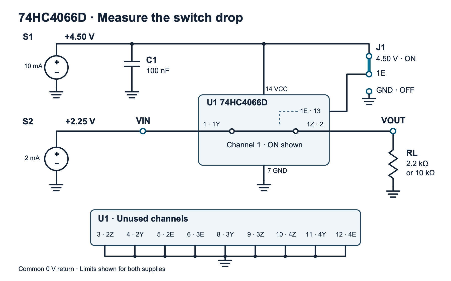
fixture.svg)| SO14 pin | What to connect |
|---|---|
| 14, VCC | S1 positive at 4.50 V. Connect the 100 nF capacitor from pin 14 to pin 7, with short leads. |
| 7, ground | S1 negative, S2 negative and the load’s lower terminal all meet here. |
| 1, 1Y | S2 positive at 2.25 V. This is the input test point, VIN. |
| 2, 1Z | Output test point, VOUT. Fit exactly one load resistor from this pin to ground. |
| 13, 1E | Middle of the jumper header. Connect its other positions to S1 positive and ground. Fit the shunt to exactly one side. |
| 5, 6, 12 | Unused enables 2E, 3E and 4E to ground. |
| 3, 4, 8, 9, 10, 11 | Both signal terminals of each unused channel to ground. |
The capacitor is decoupling, a local store of charge across the supply rails. It helps keep the chip supply stable. Grounding the unused terminals makes their voltages predictable. A high enable conducts between 1Y and 1Z. The 4.50 V rail powers the control circuit. The 2.25 V source supplies the signal current through the enabled path.
Use no negative signal voltage. Keep the shunt installed whenever the fixture is powered. Turn S1 on first and confirm the rail at pins 14 and 7 before turning S2 on. Turn S2 off and confirm its voltage falls near zero before turning S1 off. If S1 is off while S2 is still active, the signal can exceed the unpowered chip’s rail. Change loads, shunt position and wiring only with both outputs off. Keep the load in place for the disabled test.
Measure both loads under the same conditions
- Measure each loose load resistor in resistance mode. Record the actual value in ohms, then return the meter to DC voltage. With both supplies off, connect the 2.2 kΩ resistor and set J1 to ON. Check the adapter pin numbers, the common return and the unused channels.
- Follow the power sequence. Verify that both supplies remain in voltage regulation, with neither current-limit indicator active. Measure rail voltage from pin 14 to pin 7. Measure VIN from pin 1 to ground, then VOUT from pin 2 to ground. Use the 6.000 V DC range for these readings. Record settled values and the meter range.
- For the switch drop, put the red voltage lead at pin 1 and the black common lead at pin 2. Keep the battery-powered meter isolated from other equipment. First check in the DC volts range. Use the 600.0 mV DC range for a smaller settled ON drop. Record this direct voltage in millivolts (mV). If polarity or magnitude is unexpected, switch off and investigate before repeating.
- Power down, replace the 2.2 kΩ load with the 10 kΩ load, and repeat the ON measurements. Keep S2 at the same measured input voltage. Then restore the first load and repeat one run. An input change or failure to reproduce the first reading can obscure the effect of the switch.
- With both outputs off, move J1 to OFF while the 2.2 kΩ load remains fitted. Power up in order. Measure both nodes again. Use the 6.000 V DC range across the switch because the voltage between pins 1 and 2 can approach 2.25 V. Record the
offrow. Finally turn S2 off before S1.
The listed limits and ranges are chosen for a steady meter experiment. The 74HC4066 data sheet’s absolute maximum currents describe stress limits. Keep this setup near or below 1.1 mA of expected load current and leave the 2 mA signal-source limit active. Nexperia’s limiting-values footnote gives a 0.4 V maximum switch drop when current enters Y to avoid a path from the supply. The intended ON drops are much smaller. A reading near that boundary calls for power down and diagnosis before further measurements.
Calculate current and effective on-resistance
Use Ohm’s law on the measured load. Load current in amperes is IL = VOUT ÷ RL. Effective switch resistance for an ON reading is RON ≈ VDROP ÷ IL. Millivolts divided by milliamperes (mA) also gives ohms. Use the direct voltage across the switch in the numerator. The two ground-referenced readings provide a useful consistency check.
Nexperia’s Table 6 gives a typical peak of 54 Ω at 4.5 V with a 1 mA switch test current at 25 °C. For planning only, an ideal 2.250 V source and 54 Ω series resistance produce a 53.9 mV drop with 2.2 kΩ and a 12.1 mV drop with 10 kΩ. This is a series-resistor calculation. A particular chip’s resistance depends on signal voltage, supply, temperature and test conditions. A similar resistance across two runs is plausible, while equal measured resistance is unnecessary. The lower-current example applies the same illustrative resistance at a different test current.
| Load | VIN | VOUT | VDROP | IL | Effective RON |
|---|---|---|---|---|---|
| 2.200 kΩ | 2.250 V | 2.200 V | 50.0 mV | 1.000 mA | 50.0 Ω |
| 10.00 kΩ | 2.250 V | 2.238 V | 12.0 mV | 0.224 mA | 53.6 Ω |
These rows were chosen to make the arithmetic easy to check. To compare your measurements, consider the range, resolution and calibration of each reading. For the 87V MAX in the 600.0 mV DC range, resolution is 0.1 mV and the manual specifies ±(0.1% of the reading + one count) under its detailed accuracy conditions. At a constructed 12.0 mV that is about ±0.112 mV for the voltage-drop reading alone. It excludes resistor and output-voltage uncertainty, connection changes and source drift. At 2.25 V on the 6.000 V range, the allowance for one reading is about ±2.13 mV. Direct drop measurement avoids subtracting two ground-referenced readings with millivolt-scale uncertainty.
The 87V MAX nominal voltage input impedance is 10 MΩ. In parallel with a 10 kΩ load it adds about 0.1% to that branch’s conductance, its ability to pass current. With the meter across the disabled switch, the meter itself supplies a weak path from input to output. A 2.25 V drop across 10 MΩ represents about 0.225 µA through the meter. That can raise a 10 kΩ output by roughly 2.25 mV in a simple model. Keep disabled rows as circuit observations and record the actual probe placement. They cannot isolate the chip’s leakage from meter loading or the fixture’s surface leakage.
Analyze the worksheet with Python
Download the blank worksheet (ZIP: observations-blank.csv) and save a copy with your readings. The first row names the six fields. Use on or off for state, measured ohms for load_ohm, volts for rail_v, input_v and output_v, and the signed direct reading in millivolts for drop_mv. Enter a decimal point and omit unit symbols. Fill in or remove the starter rows before running the program.
Save the complete program as switch_drop.py. Use Python 3.9 or later. Run python3 switch_drop.py observations.csv in the same directory. To check your setup with the constructed numbers above, use constructed-examples.csv (ZIP: constructed-examples.csv) as input. The result is a new CSV table printed to the terminal. The program keeps the effective ON resistance blank in an OFF row or when the drop is below 1 mV. That floor is a worksheet convention to avoid turning near-zero readings into an apparently precise resistance. Use your own meter uncertainty to decide whether a result is resolved.
The analyzer checks finite readings, supply and signal ranges for this fixture, a 2 mA load-current ceiling, and agreement within 10 mV between the direct drop and VIN minus VOUT. The 10 mV screen catches unit mistakes and changes between readings. If a row fails, correct the cause and run the complete sheet again. The script prints no partial result. It checks arithmetic and input consistency, so a passing row still needs your recorded meter range and repeatability check.
"""Calculate load current and effective ON resistance for the 74HC4066 bench."""
import argparse
import csv
import math
from pathlib import Path
import sys

INPUT = ("state", "load_ohm", "rail_v", "input_v", "output_v", "drop_mv")
OUTPUT = ("state", "load_ohm", "load_current_ma",
          "effective_on_resistance_ohm", "interpretation")


def number(row, key):
    value = row[key]
    if value is None or not value.strip():
        raise ValueError(f"{key} is required")
    try:
        parsed = float(value)
    except ValueError:
        raise ValueError(f"{key} must be a number") from None
    if not math.isfinite(parsed):
        raise ValueError(f"{key} must be finite")
    return parsed


def analyze(row):
    state = row["state"]
    if state not in ("on", "off"):
        raise ValueError("state must be on or off")
    load, rail, source, output, drop_mv = (number(row, key) for key in INPUT[1:])
    if load <= 0:
        raise ValueError("load_ohm must be positive")
    if not 4.4 <= rail <= 4.6:
        raise ValueError("rail_v is outside the fixture's 4.4–4.6 V range")
    if not 0 <= source <= rail:
        raise ValueError("input_v is outside the measured supply rails")
    if not 0 <= output <= rail:
        raise ValueError("output_v is outside the measured supply rails")
    if not 2.20 <= source <= 2.30:
        raise ValueError("input_v is outside the fixture's 2.20–2.30 V range")
    if abs((source - output) * 1000 - drop_mv) > 10.0:
        raise ValueError("direct drop disagrees with input minus output by over 10 mV")
    current_ma = output / load * 1000
    if current_ma > 2.0:
        raise ValueError("calculated load current exceeds the fixture's 2 mA scope")

    resistance = ""
    interpretation = "off"
    if state == "on":
        if drop_mv < 0:
            raise ValueError("ON drop is negative. Check probe polarity or repeated readings")
        if drop_mv > 400:
            raise ValueError("ON drop exceeds 400 mV. Power down and diagnose the fixture")
        if drop_mv < 1.0 or current_ma == 0:
            interpretation = "drop_unresolved"
        else:
            resistance = f"{drop_mv / current_ma:.1f}"
            interpretation = "on_estimate"
    return (state, f"{load:g}", f"{current_ma:.6f}", resistance, interpretation)


def read_results(stream):
    reader = csv.DictReader(stream, strict=True)
    if reader.fieldnames != list(INPUT):
        raise ValueError("CSV header must be " + ",".join(INPUT))
    results = []
    for row in reader:
        try:
            if None in row:
                raise ValueError("too many columns")
            results.append(analyze(row))
        except ValueError as exc:
            raise ValueError(f"row {reader.line_num}: {exc}") from exc
    if not results:
        raise ValueError("supply at least one complete row")
    return results


def main():
    parser = argparse.ArgumentParser(description=__doc__)
    parser.add_argument("sheet", help="worksheet CSV path or - for standard input")
    args = parser.parse_args()
    try:
        if args.sheet == "-":
            results = read_results(sys.stdin)
        else:
            with Path(args.sheet).open(encoding="utf-8-sig", newline="") as stream:
                results = read_results(stream)
    except (OSError, UnicodeError, csv.Error, ValueError) as exc:
        parser.exit(2, f"{exc}\n")

    writer = csv.writer(sys.stdout, lineterminator="\n")
    writer.writerow(OUTPUT)
    writer.writerows(results)


if __name__ == "__main__":
    main()
Interpret readings that do not fit
- The enabled output stays near ground. Measure the enable voltage at pin 13. Check that pin 14 is powered, the chosen 1Y and 1Z pads are consecutive, and the adapter orientation matches the SO14 drawing. Stop if the source is current-limiting.
- The disabled output stays near the input. Check the grounded shunt position and verify that the load is actually connected to ground. An open load leaves the output dependent on stray paths and the meter. Power down and correct the load before inferring anything about isolation.
- Changing the load moves the input voltage too. Verify the S2 output setting under both loads and check for excessive source or breadboard contact resistance. Keep the direct switch drop and the input movement as separate observations. Do not fold them into one switch resistance.
- The drop is negative or changes after moving probes. Confirm red at the source-side terminal and black at the load-side terminal. Compare the direct drop with the two readings relative to ground. Repeat after settling with the same probe placement. A calculation cannot correct mixed-up units or a drifting source.
For a different analog-switch problem, see CD74HC4051: Choose a Sensor and Let the Input Settle. That experiment times how quickly an analog-to-digital converter (ADC) can read after switching between channels. Here the source stays steady and the question is how much voltage the switch loses once the readings have settled.
Challenge
In a constructed extra run, the measured load is 4.70 kΩ, VIN is 2.250 V, VOUT is 2.220 V and the direct drop is 30.0 mV. Find the load current and effective on-resistance. What additional fact would you need before calling a later reading within 1 Ω of that result equivalent?
Check your answer
2.220 V ÷ 4,700 Ω is about 0.472 mA. Then 30.0 mV ÷ 0.472 mA gives about 63.5 Ω. Compare the resistance difference with the uncertainty in both voltage readings, both load values and their repeatability. Also confirm that the supply, input and temperature were comparable. The displayed digits alone cannot establish a 1 Ω difference.
Primary references and downloads
- Nexperia 74HC4066/74HCT4066 data sheet, Rev. 12. See sections 5 and 6 for the pin assignments and enable state. Tables 4–7 cover ratings, recommended operation, on-resistance and input thresholds.
- Nexperia 74HC4066D product page and manufacturer ordering table. Check the ,653 orderable and SO14 outline before choosing an adapter.
- Fluke 87V MAX users manual, Rev. 1. Printed pages 10–11 explain voltage measurement and input loading. Pages 41 and 45 list DC accuracy and nominal voltage input characteristics.
Download the experiment files (ZIP) (ZIP: experiment-tests-v1.zip). Includes the complete Python program, host tests, blank and constructed worksheets, editable circuit and full-size image.
Download the complete reader files (ZIP): the original editable drawing, PNG, worksheet and code in 74hc4066-settled-load-drop. The full main program is also included above.