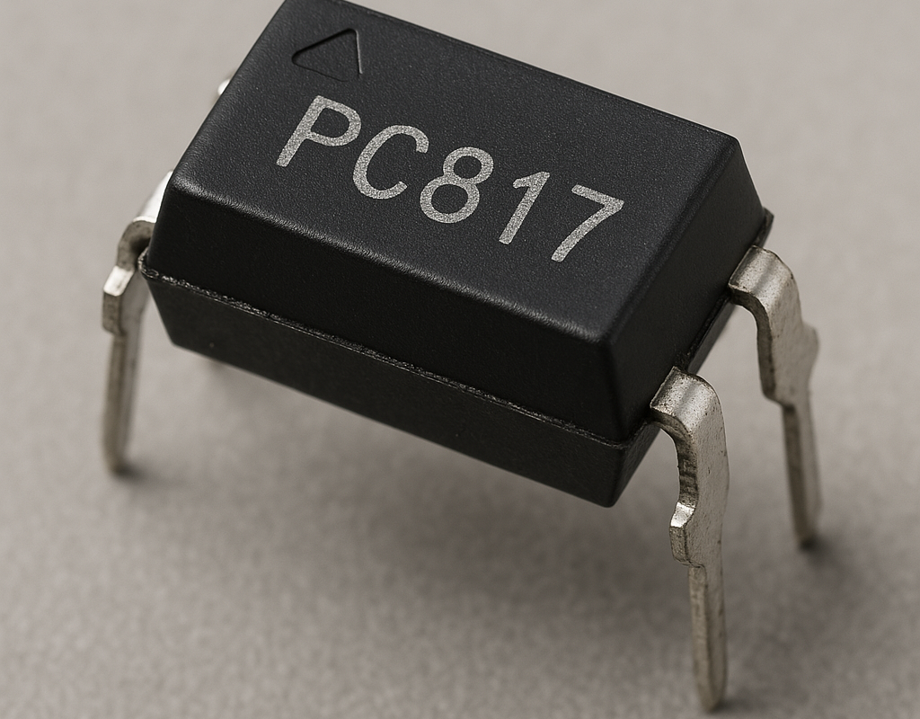
The PC817 is a phototransistor-based optocoupler (also called an optoisolator) used to provide electrical isolation between two circuits. It is widely used in signal isolation, microcontroller interfacing, power electronics, and switching applications.
🔹 1. What is the PC817?
- The PC817 consists of an infrared LED and a phototransistor in a 4-pin package.
- It isolates low-voltage control circuits (e.g., Arduino, ESP32, STM32) from high-voltage power circuits.
- Prevents electrical damage and reduces noise interference.
📌 Key Features:
- Provides electrical isolation up to 5kV.
- Can switch DC signals with low power consumption.
- Maximum Collector-Emitter Voltage (Vce): 35V.
- Current Transfer Ratio (CTR): 50-600% (Efficiency of signal transfer).
- Used in industrial automation, power supply feedback, and microcontroller protection.
📌 Why use it?
- Prevents damage between different voltage circuits.
- Reduces interference (eliminates ground loops).
- Allows communication between different voltage levels.
🔹 2. PC817 Pinout & Functions
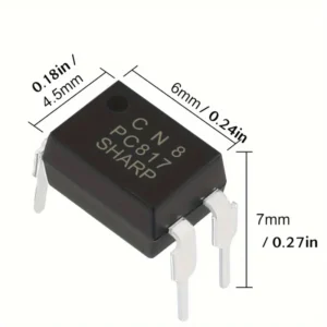
The PC817 comes in a 4-pin DIP package.
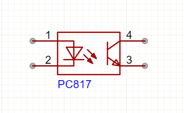
| Pin No. | Name | Function |
|---|---|---|
| 1 | Anode (A) | Positive Terminal of the LED |
| 2 | Cathode (K) | Negative Terminal of the LED (Ground) |
| 3 | Emitter (E) | Phototransistor Emitter (Output) |
| 4 | Collector (C) | Phototransistor Collector (Output) |
📌 How it works:
- Pins 1 & 2 → Control the LED inside the optocoupler.
- Pins 3 & 4 → The phototransistor switches ON/OFF based on the LED state.
🔹 3. How PC817 Works
- When current flows through the internal LED (Pins 1 & 2), it emits infrared light.
- This light activates the phototransistor (Pins 3 & 4), allowing current to pass.
- When the LED is OFF, the phototransistor is OFF, isolating the circuit.
📌 This allows a low-voltage microcontroller (e.g., Arduino) to safely switch high-voltage circuits.
🔹 4. Using PC817 for Microcontroller Isolation
🛠 Required Components
- 1x PC817 Optocoupler
- 1x 220Ω Resistor (For LED Current Limit)
- 1x 10kΩ Resistor (Pull-down for Transistor Output)
- 1x Arduino (or Any Microcontroller)
- 1x External Circuit (e.g., Relay, Motor, or High-Voltage Load)
🛠 Wiring Diagram
| PC817 Pin | Arduino Pin / External Circuit |
|---|---|
| Anode (Pin 1) | D7 (Arduino Output Pin) |
| Cathode (Pin 2) | GND (Arduino Ground) |
| Collector (Pin 4) | Relay/Motor Control Circuit |
| Emitter (Pin 3) | GND (External Circuit Ground) |
🔹 5. Arduino Code for PC817
This example turns ON/OFF a high-voltage device using an Arduino and PC817.
#define OPTOCOUPLER 7  // Connects to PC817 Anode (Pin 1)

void setup() {
    pinMode(OPTOCOUPLER, OUTPUT);
}

void loop() {
    digitalWrite(OPTOCOUPLER, HIGH);  // Turn ON the optocoupler (Activates output)
    delay(2000);  // Wait 2 seconds
    digitalWrite(OPTOCOUPLER, LOW);   // Turn OFF the optocoupler
    delay(2000);
}
📌 What happens?
- The Arduino controls the optocoupler LED.
- When the LED is ON, the phototransistor allows current flow.
- When the LED is OFF, the phototransistor is OFF (isolates the circuit).
🔹 6. Using PC817 for AC Mains Isolation (Safe Switching)
📌 PC817 can be used to switch AC appliances (e.g., lamps, fans) via a relay.
🛠 Circuit Steps
- The Arduino controls the PC817 LED.
- The PC817 phototransistor switches ON a relay.
- The relay controls the AC device.
📌 Using PC817 prevents high-voltage AC from reaching the microcontroller!
🔹 7. Applications of PC817
✅ Microcontroller Isolation – Protects Arduino from high voltage circuits.
✅ Switching High-Voltage Devices – Controls relays, motors, and power electronics.
✅ Noise Reduction – Used in industrial automation and signal isolation.
✅ AC/DC Power Control – Safe switching of mains appliances.
✅ RS232 & Serial Communication Isolation – Protects data lines from voltage spikes.
🔹 8. PC817 vs Other Optocouplers
| Feature | PC817 | 4N35 | MOC3021 (Triac) |
|---|---|---|---|
| Isolation Voltage | 5kV | 5kV | 7.5kV |
| Max Output Voltage | 35V | 70V | 400V |
| Output Type | Transistor | Transistor | Triac (For AC Control) |
| Best For | Microcontroller Isolation | Low-power isolation | AC Load Switching |
📌 Verdict:
- PC817 is best for low-power microcontroller isolation.
- 4N35 is a higher voltage alternative.
- MOC3021 is used for AC load switching (Triac control).
🎯 Conclusion
- PC817 is an optocoupler that provides electrical isolation between circuits.
- Used for switching high-power devices, protecting microcontrollers, and noise reduction.
- Works with Arduino, ESP32, STM32, and other microcontrollers.
- Prevents high-voltage damage and interference in sensitive circuits.