A short positive measuring pulse still has a preferred electrical direction. This follow-up to the one-polarity water probe reverses that direction, keeps both raw responses, and calculates a signed imbalance index. The useful result is a comparison of one recorded fixture in two directions. It is not a corrosion-free sensor, a conductivity meter or proof that equal commanded pulses transfer equal physical charge.
Use an original RP2040 Raspberry Pi Pico with the official RPI_PICO build of MicroPython 1.26.0. General-purpose input/output (GPIO) pins GP14 and GP15 provide the two current-limited drives. Two analog-to-digital converter (ADC) channels observe the electrode voltages through separate filters. Universal Serial Bus (USB) is the board’s only power input. This is a finite tabletop experiment with a little detached water, not a connection to plumbing, an energized liquid, a pump or unattended flood control.
Units used here are millimetres (mm), volts (V), ohms (Ω), kilohms (kΩ), nanofarads (nF), microamperes (µA), milliseconds (ms) and microseconds (µs).
The circuit, complete program and constructed examples have software and document checks. No target firmware build, Pico execution, wet-probe experiment or measured corrosion result is claimed. A software wait cannot impose a physical cutoff during a hung conversion or stalled interpreter. Keep the electronics dry and disconnect USB before moving wires or coupons.
1. Define the comparison before changing the circuit
The earlier ESP32 pulsed water-probe lesson explicitly retains a direct-current (DC) component. Here positive excitation means GP14 HIGH and GP15 LOW; negative excitation means the reverse. “Both LOW” is a third, active discharge state. It ties both probe branches toward the same ground through their resistors; it is not an electrically open probe or galvanic isolation. Reset or loss of power can instead make pins high impedance.
A wet bridge may respond differently because of surface films, unequal contact areas, contamination, electrode polarization or electronics error. Polarization means the electrode interface changes as charge is redistributed. A difference is a reason to investigate and repeat a controlled comparison, not a chemical diagnosis. Swapping the lead assignment helps separate a physical coupon effect from an ADC-channel or resistor effect.
2. Build and record WET-REV-A
Specify two supplier-identified 316L stainless-steel coupons, each 10 × 20 × 1 mm. Hold them coplanar with adjacent 10 × 10 mm exposed patches and a 5 mm edge gap. Insulate the other wettable surfaces, keep lead attachments dry, and put the holder in a shallow nonconductive tray. Record the stock identity, actual gap, exposed area, cleaning method, water source and temperature. If the material grade is unknown, record that limitation rather than treating a shiny metal as verified 316L.
WET-REV-A is a proposed geometry, not a manufactured probe specification or a calibrated cell constant. The gap can be dry or bridged with a small amount of water. Both a broken lead and a clean dry gap can give very little current; this topology cannot establish which one occurred. Residue may conduct after visible water is gone.
R1 and R2 are exact Vishay MRS25000C1002FCT00 10 kΩ ±1% axial resistors. R3 and R4 are MRS25000C1001FCT00 1 kΩ ±1%. In this ordering system, CT is taped fan-fold box packaging, not a different resistance. C1 and C2 are nonpolar X7R ceramic 10 nF capacitors rated at least 10 V. X7R describes a dielectric class; it does not guarantee the effective capacitance in an assembled circuit.
3. Trace both drives and both sense branches
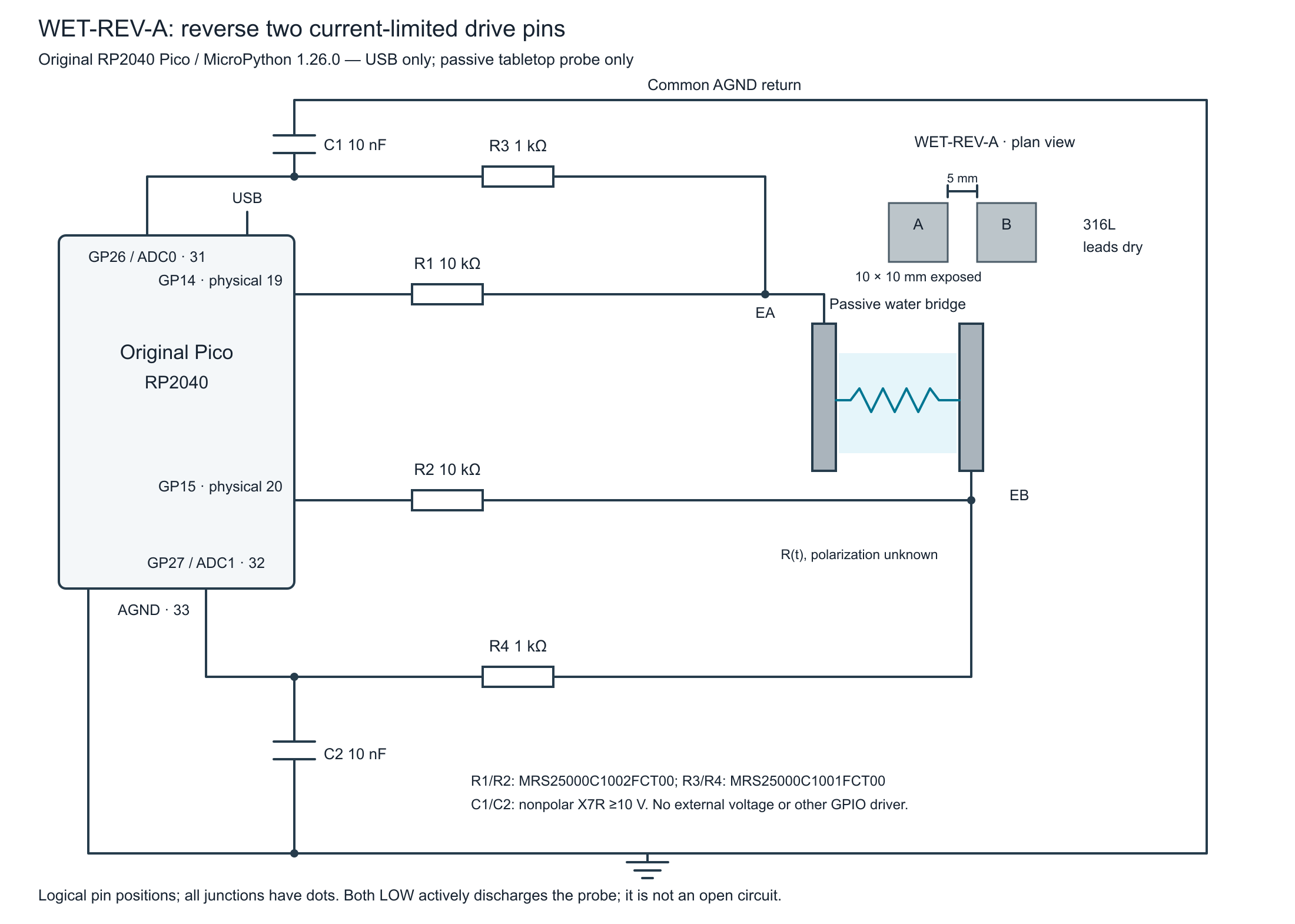
tricky-circuit-campaigns93-98/batch-010/packages/pico-leak-reversed-excitation/pico-leak-functional.svg).| Connection | Job |
|---|---|
| GP14, physical 19 → R1 10 kΩ → electrode A, EA | Positive-direction source, or low return during the negative direction. |
| GP15, physical 20 → R2 10 kΩ → electrode B, EB | Negative-direction source, or low return during the positive direction. |
| EA → R3 1 kΩ → GP26 / ADC0, physical 31 | Sense A through a separate series resistor. |
| EB → R4 1 kΩ → GP27 / ADC1, physical 32 | Sense B through a separate series resistor. |
| C1 10 nF: ADC0 node → AGND 33 | Local capacitive reservoir/filter for the A reading. |
| C2 10 nF: ADC1 node → AGND 33 | Equivalent filter for the B reading. |
No electrode has a direct ground wire. The only intentional conduction path between the drive branches is the passive wet bridge. The 1 kΩ sense resistors are not complete overvoltage protection. Keep both ADC inputs within the powered board’s permitted analog range and no higher than its input/output supply, IOVDD; analog supply ADC_AVDD can differ from IOVDD. Never attach another powered sensor output, signal generator or externally energized water to these contacts, including when the Pico is unpowered.
Before connecting the wet fixture, substitute a dry 20 kΩ resistor between EA and EB. Use suitable high-impedance oscilloscope probes at the actual GPIO terminals, referenced to AGND, to observe loaded HIGH and LOW levels during the finite pulses. A digital multimeter (DMM) averages these pulses and cannot certify their individual levels; no separate static-drive program is supplied here. Do not join a second push-pull driver to a Pico output. The MicroPython program is the sole owner of GP14, GP15 and the ADC during its run; no other thread, interrupt routine or concurrent program may reconfigure them.
4. Calculate limits without declaring an accurate meter
With an ideal 3.3 V source and a near-zero-resistance wet bridge, the two 1% 10 kΩ drive resistors give approximately 3.3 / (9.9k + 9.9k) = 166.7 µA. An initial filter-capacitor or one-branch fault current can instead approach 3.3 / 9.9k = 333 µA. These are different paths, calculated at an assumed rail. Neither is a guarantee for a higher supply or an externally powered probe.
The ideal source resistance seen by either 10 nF filter is at most approximately 10 kΩ plus its 1 kΩ sense resistor. Its resistance-capacitance (RC) time constant is therefore approximately 110 µs nominal. The program waits 5 ms after changing direction, then takes late readings. That interval covers the simple electrical model; it does not prove that electrode chemistry, stray capacitance or all leakage has settled. Compare actual traces and repeated windows before trusting a wet result.
The RP2040 uses a successive-approximation-register (SAR) ADC. Its small sampling capacitor does not turn a resistor-fed input into an ideal voltage source. The datasheet’s acquisition discussion and E11 nonlinearity erratum still apply. The pinned firmware scales a 12-bit result to read_u16() by bit replication; 0–65535 output is not 16-bit analog accuracy. It also does not automatically establish a valid conversion simply because the returned number is in range.
The program clears internal pulls by configuration and checks the ADC control/status register around each read. It rejects observed conversion-error flags and competing continuous/round-robin operation without clearing an error. This does not prove continuous ownership between checks or a healthy analog signal. Stop after an error, inspect the cause and begin a fresh run; do not silently erase the evidence.
5. What the signed index actually measures
For the positive direction the low electrode is B; for the negative direction it is A. The program reads that low leg first in either direction. The first output uses an assumed reference voltage (VREF) of 3.3 V and nominal 10 kΩ drive resistors. It converts the low-leg code to that voltage scale, then divides by the corresponding resistor value; these defaults are not measured calibration. This is a current-shaped numerical proxy:
V_LOW_PROXY = assumed_VREF × raw_low / 65535
I_LOW_PROXY = V_LOW_PROXY / R_LOW
Q_LATE_PROXY = Σ ½ × (I[k−1] + I[k]) × (t[k] − t[k−1])
SIGNED_PROXY = Σ Q_positive − Σ Q_negative
IMBALANCE = SIGNED_PROXY / (Σ Q_positive + Σ Q_negative)
The trapezoids cover only the timestamps between the eight late low-leg reads. Their unit is coulombs (C), usually displayed as microcoulombs (µC), because amperes are multiplied by seconds. The quantity remains an inferred numerical index, not measured total electrode charge. The timestamps bracket host read calls; the chosen integration points are their completion times, not exact hardware sampling apertures. No contribution before the first or after the last late sample is included.
The low GPIO’s actual output voltage, ADC offsets/nonlinearity, reference error, input leakage, filter-capacitor current and sequential-read skew all affect that proxy. For scale, 1 µA through 11 kΩ gives an 11 mV illustrative error contribution; it is not a calibration or a guaranteed ADC-only leakage estimate. Verify loaded drive levels, actual VREF and resistor values with suitable instruments if attempting a more quantitative experiment.
An all-zero denominator produces imbalance_index: null, not “perfect balance.” Codes at either rail are retained with rail_code_observed; they do not prove dry, unplugged, shorted or healthy status. A failed run discards its partial software result, but cannot undo physical polarization that happened before the error.
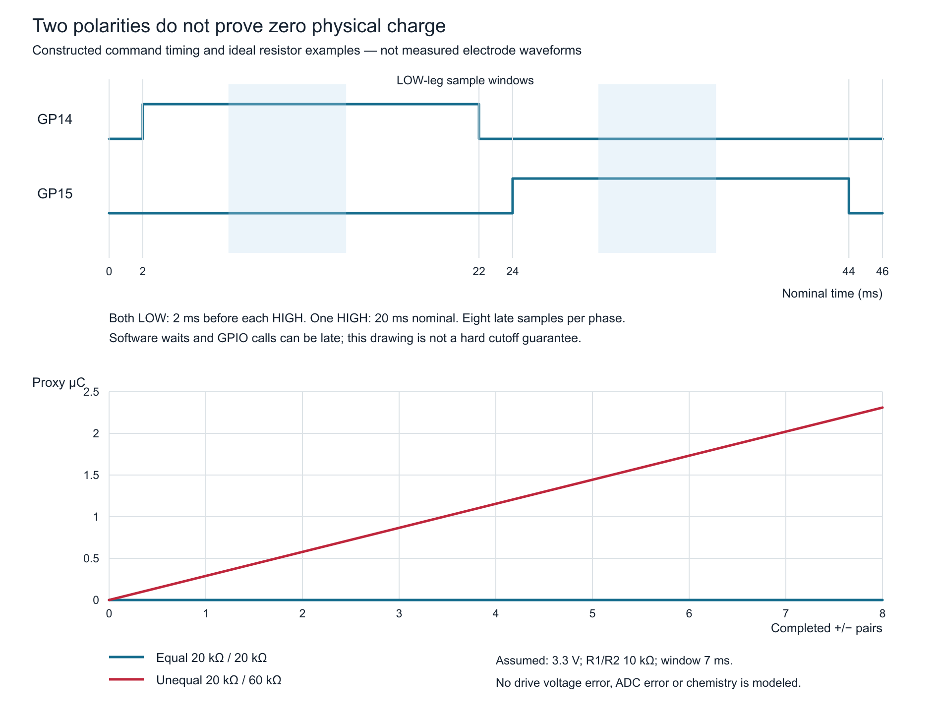
tricky-circuit-campaigns93-98/batch-010/packages/pico-leak-reversed-excitation/pico-leak-proxy.svg).In the ideal 20 kΩ bridge example, each direction draws 3.3/(10k + 20k + 10k) = 82.5 µA. A constructed 60 kΩ reverse response gives 41.25 µA. Equal 7 ms late windows then produce a positive signed proxy of 0.28875 µC per pair, or 2.31 µC after eight pairs. This deliberately asymmetric model illustrates the arithmetic; it does not predict an electrode’s electrochemical behavior.
6. Complete finite MicroPython program
Save pico-leak-reversed-excitation.py (ZIP; file: tricky-circuit-campaigns93-98/batch-010/packages/pico-leak-reversed-excitation/pico-leak-reversed-excitation.py) on the selected Pico. Keep it separate from main.py, so connecting USB does not automatically start excitation. After wiring checks, use this exact block in the read-evaluate-print loop (REPL), the interactive MicroPython console, to execute one finite run:
scope = {"__name__": "__main__"}
with open("pico-leak-reversed-excitation.py") as f:
    exec(f.read(), scope)
Each direction starts with both LOW for at least 2 ms, then one HIGH for a nominal 20 ms. After the 5 ms filter wait, eight low-first reading pairs are taken. Extra conversions are discarded, without claiming calibration. Returned GPIO-command spans above 500 µs or a full observed HIGH bracket above 25 ms reject the run. A hung ADC read or interpreter pause can still leave a drive active until execution resumes; the code supplies no independent hardware watchdog cutoff.
"""WET-REV-A, original Pico / MicroPython 1.26.0. Finite experiment.
GP14--10k--EA--water--EB--10k--GP15. EA/EB--1k--ADC0/1,
10nF from each ADC node to AGND. No external powered probe.
LOW is an active discharge command, not electrical isolation.
Late-window V/R integrals are numerical proxies, NOT total charge.
"""
import math


def finite(value, name, low, high):
    if type(value) not in (int, float):
        raise ValueError(name)
    try:
        value = float(value)
    except (OverflowError, ValueError):
        raise ValueError(name)
    if not math.isfinite(value) or not low <= value <= high:
        raise ValueError(name)
    return value


def raw(value):
    if type(value) is not int or not 0 <= value <= 65535:
        raise ValueError("ADC_API_VALUE")
    return value


class Clock:
    def __init__(self, ticks, difference):
        self.ticks, self.difference = ticks, difference
        self.last, self.total, self.fault = None, 0, False

    def now(self):
        if self.fault:
            raise ValueError("CLOCK_FAULT")
        try:
            r = self.ticks()
            if type(r) is not int:
                raise ValueError("CLOCK_TYPE")
            if self.last is not None:
                d = self.difference(r, self.last)
                if type(d) is not int or not 0 <= d <= 100000:
                    raise ValueError("CLOCK_GAP")
                self.total += d
            self.last = r
            return self.total
        except BaseException:
            self.fault = True
            raise


def wait_at_least(us, clock, sleep):
    start = clock.now()
    sleep(us)
    end = clock.now()
    if end - start < us:
        raise ValueError("EARLY_WAIT_OR_FROZEN_CLOCK")
    return end


class Hardware:
    def __init__(self, Pin, ADC, mem32):
        self.Pin, self.ADC, self.mem32 = Pin, ADC, mem32
        self.a, self.b, self.adc_a, self.adc_b = None, None, None, None

    def open(self):
        self.a = self.Pin(14, self.Pin.OUT, value=0)
        self.b = self.Pin(15, self.Pin.OUT, value=0)
        self.Pin(26, self.Pin.IN, pull=None)
        self.Pin(27, self.Pin.IN, pull=None)
        self.adc_a, self.adc_b = self.ADC(26), self.ADC(27)
        # RP2 adc_gpio_init also disables digital input and internal pulls.
        self.check_adc()

    def low(self):
        first = None
        for n, pin in ((14, self.a), (15, self.b)):
            try:
                if pin is None:
                    self.Pin(n, self.Pin.OUT, value=0)
                else:
                    pin.value(0)
            except BaseException as e:
                if first is None:
                    first = e
        if first is not None:
            raise first

    def high(self, direction):
        if direction == 1:
            self.a.value(1)
        elif direction == -1:
            self.b.value(1)
        else:
            raise ValueError("DIRECTION")

    def check_adc(self):
        # Read-only RP2040 ADC CS: require EN, no continuous/round-robin owner,
        # and no current or sticky conversion error. Never clear an error here.
        status = self.mem32[0x4004C000]
        if type(status) is not int or not 0 <= status <= 0xFFFFFFFF:
            raise ValueError("ADC_STATUS_TYPE")
        if not status & 1 or status & ((1 << 3) | (1 << 9) |
                                      (1 << 10) | (31 << 16)):
            raise ValueError("ADC_STATUS_OR_CONCURRENT_OWNER")

    def read(self, leg):
        if leg not in ("A", "B"):
            raise ValueError("ADC_LEG")
        self.check_adc()
        value = (self.adc_a if leg == "A" else self.adc_b).read_u16()
        self.check_adc()
        return raw(value)


def summarize(rows, reference_v=3.3, r_a=10000, r_b=10000):
    """Trapezoids ONLY between actual late low-leg read timestamps.

    Assumes reference scale and zero low-driver voltage; ignores ADC error,
    filter/probe currents and intersample chemistry. Not physical charge.
    """
    ref = finite(reference_v, "reference_v", 3.0, 3.6)
    ra = finite(r_a, "r_a", 9900, 10100)
    rb = finite(r_b, "r_b", 9900, 10100)
    if type(rows) is not list or not 2 <= len(rows) <= 16 or len(rows) % 2:
        raise ValueError("COMPLETE_PAIRS_REQUIRED")
    totals = {1: 0.0, -1: 0.0}
    phases = []
    for index, row in enumerate(rows):
        direction = 1 if index % 2 == 0 else -1
        if row["pair"] != index // 2 or row["direction"] != direction:
            raise ValueError("PAIR_ORDER")
        samples = row["samples"]
        if len(samples) != 8:
            raise ValueError("INCOMPLETE_PHASE")
        currents, times, endpoints = [], [], False
        for s in samples:
            lo, hi = raw(s["low_u16"]), raw(s["high_u16"])
            tt = s["low_after_us"]
            if type(tt) is not int or tt < 0 or (times and tt <= times[-1]):
                raise ValueError("SAMPLE_TIME_ORDER")
            times.append(tt)
            currents.append(ref * lo / 65535 / (rb if direction == 1 else ra))
            endpoints = endpoints or lo in (0, 65535) or hi in (0, 65535)
        integral = sum((a + b) * .5 * (tb - ta) / 1000000
                       for a, b, ta, tb in zip(currents, currents[1:],
                                               times, times[1:]))
        totals[direction] += integral
        phases.append(dict(pair=row["pair"], direction=direction,
                           mean_low_leg_proxy_a=sum(currents) / 8,
                           late_window_proxy_c=integral,
                           sampled_window_us=times[-1] - times[0],
                           rail_code_observed=endpoints))
    denominator = totals[1] + totals[-1]
    return dict(scope="LATE-WINDOW NUMERICAL PROXY, NOT TOTAL ELECTRODE CHARGE",
                assumed_reference_v=ref, r_a_ohms=ra, r_b_ohms=rb,
                positive_late_proxy_c=totals[1],
                negative_late_proxy_c=totals[-1],
                signed_late_proxy_c=totals[1] - totals[-1],
                imbalance_index=((totals[1] - totals[-1]) / denominator
                                 if denominator else None),
                phases=phases, raw_phases=rows)


def capture(io, clock, sleep, pairs=8):
    rows = []
    try:
        if type(pairs) is not int or not 1 <= pairs <= 8:
            raise ValueError("PAIR_COUNT")
        for pair in range(pairs):
            for direction in (1, -1):
                io.low()
                wait_at_least(2000, clock, sleep)
                before_high = clock.now()
                io.high(direction)
                after_high = clock.now()
                if after_high - before_high > 500:
                    raise ValueError("HIGH_COMMAND_SPAN")
                wait_at_least(5000, clock, sleep)
                samples = []
                low, high = ("B", "A") if direction == 1 else ("A", "B")
                for k in range(8):
                    if clock.now() - after_high > 25000:
                        raise ValueError("PHASE_OVERRUN")
                    io.read(low)  # discard an extra conversion, not a calibration
                    wait_at_least(100, clock, sleep)
                    begin = clock.now()
                    lv = io.read(low)
                    end = clock.now()
                    io.read(high)
                    wait_at_least(100, clock, sleep)
                    hv = io.read(high)
                    finish = clock.now()
                    if end - begin > 500 or finish - end > 1000:
                        raise ValueError("READ_SPAN")
                    samples.append(dict(low_u16=raw(lv), high_u16=raw(hv),
                                        low_before_us=begin, low_after_us=end,
                                        high_after_us=finish))
                    if k != 7:
                        wait_at_least(800, clock, sleep)
                remaining = 20000 - (clock.now() - after_high)
                if remaining > 0:
                    wait_at_least(remaining, clock, sleep)
                before_low = clock.now()
                io.low()
                after_low = clock.now()
                if (after_low - before_low > 500 or
                        after_low - before_high > 25000 or
                        not 20000 <= before_low - after_high):
                    raise ValueError("PHASE_DURATION")
                rows.append(dict(pair=pair, direction=direction,
                                 before_high_us=before_high,
                                 after_high_us=after_high,
                                 before_low_us=before_low,
                                 after_low_us=after_low, samples=samples))
        return summarize(rows)
    finally:
        io.low()  # independent attempts on both outputs; failure propagates


def ohmic_model(water_plus, water_minus, reference_v=3.3,
                r_a=10000, r_b=10000, window_s=.007):
    """Ideal two-resistor example; no electrochemistry or ADC model."""
    vp = finite(reference_v, "reference_v", 3, 3.6)
    ra = finite(r_a, "r_a", 9900, 10100)
    rb = finite(r_b, "r_b", 9900, 10100)
    plus = finite(water_plus, "water_plus", 0, 1e9)
    minus = finite(water_minus, "water_minus", 0, 1e9)
    dt = finite(window_s, "window_s", .001, .02)
    ip, im = vp / (ra + plus + rb), vp / (ra + minus + rb)
    return dict(positive_a=ip, negative_a=im,
                signed_window_proxy_c=(ip - im) * dt,
                imbalance_index=(ip - im) / (ip + im))


def main():
    from machine import Pin, ADC, mem32
    from time import ticks_us, ticks_diff, sleep_us
    import json
    io = Hardware(Pin, ADC, mem32)
    try:
        io.open()
        record = capture(io, Clock(ticks_us, ticks_diff), sleep_us)
        # Both outputs have received LOW commands before any console output.
        print(json.dumps(record))
        return record
    finally:
        io.low()


if __name__ == "__main__":
    main()
The program emits one JavaScript Object Notation (JSON) record after the finite capture and its LOW cleanup have completed. The outer finalizer attempts LOW again after printing. If that later attempt fails, the already printed record remains a historical completed capture; the program raises and does not confirm the current electrical LOW state. Any failed LOW write makes the physical state uncertain. Disconnect USB and investigate rather than treating an exception as proof that the pins are safe.
For optional offline reanalysis on a computer, save the unedited JSON line as capture.json beside the program, then run the following in Python 3. The shown values are still nominal placeholders; replace them only with your own recorded reference and resistor values. Loading with runpy does not invoke main() or access hardware:
import json, runpy
analysis = runpy.run_path("pico-leak-reversed-excitation.py")
with open("capture.json") as f:
    saved = json.load(f)
result = analysis["summarize"](saved["raw_phases"],
                               reference_v=3.3, r_a=10000, r_b=10000)
7. Repeatable bench comparison and fault cases
- With USB disconnected, verify the six external circuit connections, resistor values, both capacitors and coupon separation. Keep Pico and USB connectors outside the tray. Begin with the dry 20 kΩ substitution resistor rather than water.
- Run once and retain the complete raw JSON, actual drive brackets, individual sample times, rail flags and both resistor values. Compare positive and negative phases within the same finite run. Do not replace raw values with only the final index.
- Open the substitute bridge and repeat. A low response demonstrates only this wiring state; it does not qualify unplugged-versus-dry detection. A saturated high-leg code should remain visible in the record.
- Power off, install WET-REV-A, and record its actual material, area, gap and cleaning. Add enough detached water to bridge the exposed patches, then perform one finite run. Do not touch or rearrange the wet contacts while powered.
- Disconnect power, swap A/B coupon leads at the dry connections, and repeat with the same water and geometry. If an imbalance follows one physical coupon, that is useful evidence; it still does not uniquely identify chemistry, contamination or corrosion.
- Compare early and later finite runs only while recording elapsed rest time and temperature. Avoid repeated automatic runs. Change one documented condition at a time, and preserve an unexpected sign rather than forcing a “balanced” result.
- Interrupt a dry-resistor run from the console. Verify both actual output levels afterward if testing cleanup behavior. A successful software LOW command is not voltage readback, and a host-injected exception is not this physical test.
The blank worksheet (ZIP; file: tricky-circuit-campaigns93-98/batch-010/packages/pico-leak-reversed-excitation/observations-blank.csv) has headings only. Store its rows with the unedited JSON record and instrument notes; no fabricated wet examples are supplied. The actual-code host tests (ZIP; file: tricky-circuit-campaigns93-98/batch-010/packages/pico-leak-reversed-excitation/test_excitation.py) cover phase order, breaks, nominal arithmetic, ADC errors, timing boundaries and exceptions, including errors after a GPIO write’s side effect. They do not build firmware or execute the Pico.
8. Keep the limitations in the result
A reversed command alone cannot establish zero DC offset, zero electrolysis or corrosion prevention. Unequal durations, output levels and interface history may still produce imbalance, and the late-window index omits much of each pulse. The clock check rejects observed backward or excessive gaps, but an entirely unseen modular tick wrap can alias the same raw value; normal servicing within the clock’s half-period remains an assumption.
This experiment leaves no GPIO output HIGH after successful cleanup, but both LOW is still an active electrical connection. Do not leave the probe installed as a long-term detector. For actual conductivity work, excitation offset, cell constant, temperature, calibrated front-end behavior and all acquisition errors need a different level of qualification. The Analog Devices reference explains that design problem; it does not certify this Pico fixture.
9. Challenge
Two phases have identical commanded 20 ms duration. Their low-leg readings differ, but their final signed late-window proxy is zero after rounding. Does that establish corrosion-free operation?
Show the answer
No. Commands do not verify equal actual voltage or charge. The index samples only late intervals, includes electronics error, and may hide a small difference through rounding. Earlier transient and unobserved current are excluded. Keep the raw readings and timing, report the numerical scope, and investigate the fixture without converting a zero index into an electrochemical guarantee.
10. Primary references and further study
- RP2040 datasheet, build 2025-02-20: ADC acquisition, analog voltage limits, error flags, electrical characteristics and errata E6/E11.
- Original Raspberry Pi Pico pinout: physical GPIO, ADC and AGND terminals.
- Vishay MRS16/MRS25, document 28724: part numbering, tolerances and packaging.
- MicroPython 1.26 ADC interface and pinned RP2 implementation: input initialization and 12-bit-to-16-bit scaling.
- Analog Devices CN0359: alternating conductivity excitation and polarization considerations in a substantially different precision instrument.
Explore the electronics course, ADC lesson and voltage-divider lesson before interpreting these two resistor-fed observations.
Download the complete reader files (ZIP): full programs, blank observation worksheets, original editable SVG/PNG diagrams and selected support files for pico-leak-reversed-excitation. Inline main programs remain complete; this download is supplementary.