Four buttons normally consume four digital inputs. A resistor network can encode them as four different voltages on one analog input instead. The price is ambiguity when buttons are pressed together and a need to inspect the actual values. This experiment makes both sides of that tradeoff visible.
One divider selected by each button
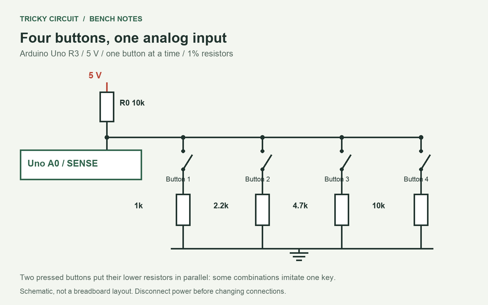
When no button is pressed, the shared 10 kΩ resistor pulls A0 toward 5 V. Each pressed button connects a different lower resistance to ground. The ADC, or analog-to-digital converter, measures the divider midpoint. On the Uno R3 with its default reference and resolution, the nominal code spans 0 to 1023.
The formula is code ≈ 1023 × Rlower/(10,000 + Rlower). Because the network and reference use the same supply, ideal supply variation largely cancels in the ratio. That does not remove resistor tolerances, contact resistance or converter error. This article targets Uno R3; a board with another input limit or resolution needs new wiring and decision windows.
Parts to gather
- Arduino Uno R3 with its normal 5 V analog reference, USB cable and Arduino IDE
- Four normally open pushbuttons
- 1% resistors: two 10 kΩ, one 1 kΩ, one 2.2 kΩ and one 4.7 kΩ
- Breadboard and jumper wires
Complete connections
| Connection | Purpose |
|---|---|
| Uno 5V → R0 10 kΩ → SENSE → A0 | R0 is the shared upper resistor and remains connected for every button. |
| SENSE → button 1 → 1 kΩ → GND | First independent lower branch. |
| SENSE → button 2 → 2.2 kΩ → GND | Second independent lower branch. |
| SENSE → button 3 → 4.7 kΩ → GND | Third independent lower branch. |
| SENSE → button 4 → 10 kΩ → GND | Fourth independent lower branch. All branches share SENSE and GND. |
Calculated targets and accepting windows
| Button | Lower resistance | Nominal code | Example window |
|---|---|---|---|
| 1 | 1 kΩ | 93 | 75–110 |
| 2 | 2.2 kΩ | 184.5 | 165–205 |
| 3 | 4.7 kΩ | 327.1 | 300–355 |
| 4 | 10 kΩ | 511.5 | 480–545 |
| None | Open | Near 1023 | 975–1023 |
A window means an accepted interval around a target. Gaps become -1, meaning invalid or uncertain. This is more informative than always selecting whichever button happens to be nearest. The listed windows are starting choices for 1% parts and short wiring; print and inspect your real raw readings before relying on them.
Complete Arduino sketch
/* Uno R3: 5V -> 10k -> A0. Four branches from A0 to GND:
 * button + 1k; button + 2.2k; button + 4.7k; button + 10k.
 * One button at a time. These are example windows for 1% resistors.
 */
int decodeButton(int raw) {
  if (raw >= 975) return 0;
  if (raw >= 75 && raw <= 110) return 1;
  if (raw >= 165 && raw <= 205) return 2;
  if (raw >= 300 && raw <= 355) return 3;
  if (raw >= 480 && raw <= 545) return 4;
  return -1;
}
int candidate = -2, stable = -2;
unsigned long since = 0, lastPrint = 0;
void setup() { Serial.begin(115200); }
void loop() {
  int raw = analogRead(A0);
  int value = decodeButton(raw);
  unsigned long now = millis();
  if (value != candidate) { candidate = value; since = now; }
  if (now - since >= 30 && stable != candidate) {
    stable = candidate;
    Serial.print("button="); Serial.println(stable);
  }
  if (now - lastPrint >= 250) {
    Serial.print("raw="); Serial.println(raw); lastPrint = now;
  }
  delay(2);
}
Build and run
- Disconnect USB and build R0 first. Add each independent button-resistor branch. On four-leg tactile switches, check which two legs are already joined internally; connect across the switching pair.
- Select Arduino Uno in the Arduino IDE, save the sketch in a folder with the same base name and upload it.
- Open Serial Monitor at 115200 baud. No button should report 0 with raw values near full scale.
- Press each button separately and record the raw range. Release between tests.
- The state must remain unchanged for at least 30 ms before it is accepted. This debounce interval suppresses brief contact chatter without blocking the main loop for the entire wait.
Try the failure on purpose
Hold buttons 1 and 4 simultaneously. Their lower resistors become parallel: 1 kΩ || 10 kΩ = about 909 Ω, giving a nominal code near 85.3. That falls inside button 1’s window. The circuit therefore cannot reliably report multiple simultaneous presses, and no software rule can recover information that the selected resistor values failed to encode distinctly.
For a menu with deliberate one-at-a-time operation, that limitation may be acceptable. For a musical keyboard, game controller or safety-related input, choose a topology that represents simultaneous states explicitly, such as separate digital inputs or a properly designed scanned matrix. Do not label every out-of-window value a fault while claiming in-window values must be correct.
Check current and wiring
The lowest normal branch is 1 kΩ, so supply current is about 5/11,000 = 0.455 mA. Even a direct SENSE-to-ground short is limited by R0 to 0.5 mA. A0 is used only as an input. If all buttons read full scale, look for a missing common ground or a switch connected across its already-common terminals. If none reads full scale, check for an unintended permanently connected branch.
Challenge: can wider windows fix simultaneous presses?
No. Wider windows can accommodate component variation but may accept more ambiguous combinations. You need an encoding circuit with enough distinguishable states, or a different input method.
Sources and related learning
Explore the Tricky Circuit interactive lessons. This article presents a design and software checks; no physical build results are claimed.