Resistors · a low-power thermal step
Turn on a small measured electrical load, then turn it off. Watch a ceramic test piece warm and cool while a second piece tracks the room. Compare when the electrical input changes with when the temperature readings move.
Follow the input and the response separately
A watt (W) is one joule of energy transferred per second. A resistor turns electrical power into heat. When you switch on, its electrical input can settle long before heat spreads through the body, leads, support and temperature probe. This lesson measures those quantities separately with an exact Vishay PR02000201000JR500, a 100 Ω axial metal-film resistor. Axial leads emerge from opposite ends of its body.
The temperature reading is taken on a ceramic coupon, a small flat test piece, beneath the resistor. A matched unheated coupon provides a reference. A thermocouple uses the voltage from a junction of two dissimilar metals to infer temperature. Its contact layer and placement affect what it reads and how quickly it follows a change. The result is a record of this fixture, mount and probes. Start with the site’s power lesson if you want to review voltage, current and rated dissipation. A resistor has a heat budget
Build the two measurement paths
- One Vishay PR02000201000JR500. Vishay’s order code gives the PR02 body, axial 0.78 mm copper leads, 100 Ω nominal and ±5% tolerance. The R5 field is the reel packaging code. The datasheet lists 2 W rated dissipation at 70 °C for this value and copper-lead PR02 configuration under its stated conditions.
- One 10.00 Ω ±0.1% sense resistor rated at least 0.25 W, kept away from both coupons. A sense resistor gives a voltage proportional to the circuit current.
- An isolated regulated direct-current (DC) bench supply. Set 3.30 V and verify a 35 mA current limit using the supply’s documented setup. A milliampere (mA) is one thousandth of an ampere.
- Two battery-operated voltage meters with approximately 10 MΩ input impedance and millivolt resolution on the sense reading. Two Fluke 87V MAX meters meet these conditions. Use their DC voltage settings, with red leads in voltage jacks and black leads in common (COM) jacks.
- Two Omega SA1-K-SRTC Type K self-adhesive thermocouples and one Fluke 52 II dual-input thermometer. Each probe has a junction laminated above an electrically insulating polyimide film and a Type K miniature connector. Connect the heater coupon to T1 and the reference coupon to T2. Use °C, Type K and zero user offset on both channels.
- Two matching flat alumina ceramic coupons, approximately 30 × 25 × 0.5 mm, ceramic supports, thin polyimide electrical tape, insulated terminal clips and a stopwatch. Use undamaged coupons with smooth edges.
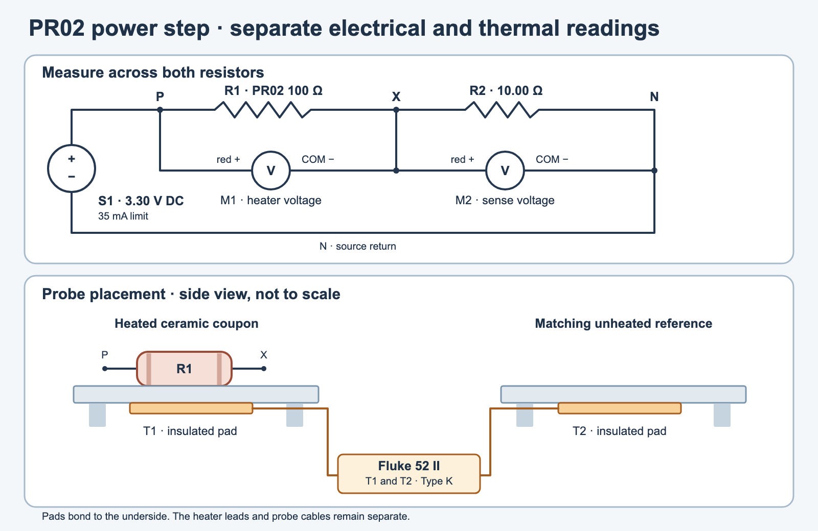
fixture.svg)| Node | Connect |
|---|---|
| P | Source positive, one PR02 lead, red lead of voltage meter M1. |
| X | Other PR02 lead, one sense resistor lead, black COM lead of M1, red lead of M2. |
| N | Other sense resistor lead, source negative, black COM lead of M2. |
Both resistors have interchangeable electrical leads. M1 reads across the heater from P to X. M2 reads across the sense resistor from X to N. The meter at X on M1 is battery-operated and floats with respect to the other meter. Use the two independent meters shown. A common-ground scope or shared-ground multichannel meter can short X to N through its ground leads.
Bond each Omega pad once to a clean flat underside as instructed. On the heated coupon, center the PR02 body directly above the pad with dry contact and two narrow tape bands around the body ends. Keep its metal leads clear of the coupon edges, supports and probe cable. Clamp each lead about 15 mm from the body at an insulated terminal and record the actual spacing. The second coupon uses matching supports and orientation about 10 cm away in the same air, with no heater. Keep both out of drafts and direct sunlight. The pad, tape, lead length and support all provide paths for heat to flow.
Measure the nominal 90 mW input
With nominal values, the two resistors total 110 Ω and draw 3.30 V ÷ 110 Ω = 0.0300 A. The heater sees 3.00 V and takes 0.090 W, or 90 milliwatts (mW). The sense resistor sees 0.300 V and takes 9 mW. At the PR02’s cold tolerance endpoints of 95 Ω and 105 Ω, with exact 3.30 V and 10.00 Ω, the predicted heater input spans about 86.5 to 93.8 mW.
Measure the heater voltage VH and sense voltage VS on each powered row. For sense resistance RS, estimate current as VS ÷ RS and heater power as VH × VS ÷ RS. This separates changes in electrical input from changes in temperature. A 10 MΩ meter across 3 V draws about 0.3 µA, where a microampere (µA) is one millionth of an ampere. Its loading is small beside 30 mA. Use the marked sense resistance and tolerance unless you have an adequately precise independent measurement.
The source is set to a fixed voltage. The measured voltages tell you how constant the actual power was. Vishay’s power and thermal data apply to specified test and mounting conditions. The temperature measured here belongs to the mounted coupon and its probe. The reading can continue rising after switch-off as heat still moves through the assembly.
Record baseline, heating and cooling
- Inspect with the output disabled. Verify the two meter sockets, P/X/N routing and heater resistance before connection. Confirm that the fixture sits stably on a nonflammable surface and both probes respond. Compare their readings side by side before final mounting, then preserve the mounted geometry throughout the run. Record room conditions, probe locations, lead spacing and the sense resistor value.
- Record three or more baseline samples. At ordinary indoor temperatures, approximately 18–26 °C, wait for both mounted readings to settle. Record time, both temperatures and both voltage readings every 10 s for at least 30 s. Compute the median, or middle value, of T1 minus T2. Use it to zero the starting difference between the channels.
- Switch on once. Keep both meters connected and record the real switch-on time as zero. Check that the supply remains in its voltage-regulating mode. Note the heater and sense readings just after the change and take further paired readings about every 20 s. Record the actual times. Keep both voltage meters and both thermometer channels visible so you can take each row in quick succession. Use an alarm at 175 s and switch off by 180 s, even if the reading is still rising.
- Watch the stop limits in real time. Switch off immediately if T1 reaches 35 °C, if T1 minus T2 rises by 10 °C above its baseline, if the source enters current limit, if heater power exceeds 0.105 W, or if a probe detaches or a connection becomes unstable. Keep hands clear of the heater and connections during the run. The temperature stop is based on the indicated coupon response. Let all parts return to room conditions before handling the fixture. If the rise is small, retain the result at this setting.
- Watch cooling with the output off. Record the actual switch-off time. Keep the same wiring and probe placement and continue recording every 20–30 s for at least three minutes. If the response takes longer, continue with the output disabled. Record the off-phase voltage readings. Keep the safety-stop reason in your notes if the run ended early.
Use the blank bench worksheet (ZIP: observations-blank.csv). Its first two columns are a suggested sample plan. Replace times with your actual timestamps and keep the baseline, heating and cooling labels aligned with the two actual switch times. Leave no empty voltage or temperature field in an analyzed row. Keep at least three rows in each phase. The two off-phase voltage readings should be within ±0.010 V.
Find a response marker without assuming equilibrium
Subtract T2 from T1 at each time. Then subtract the median baseline difference. The result is the temperature rise of the heated coupon relative to the reference and their initial offset. A shared change in room temperature often moves both readings in the same direction. This correction helps with that common change. A draft on only one coupon or a changed mounting contact can still shift the result.
The program reports the median heater power and its spread, the median rise of the last three powered samples, and the highest reading of the corrected cooling phase. The last powered median describes the end of this recording window. Half that value gives a reference for bracketing the first observed upward crossing during heating and downward crossing during cooling. Each bracket uses two real samples in its own phase. A missing bracket stays unresolved if the first sample has already passed the level or no two samples bracket it.
Thermal markers are withheld when the recorded temperature stop is reached, when heater-power spread exceeds 5% of its median, or when the rise is too small for the worksheet’s screening rule. The baseline spread must be at most 0.5 °C. The last powered median must reach at least 1.0 °C and at least three times that spread. These checks screen obvious problems. Evaluate your probe repeatability and time sampling before treating a small difference as resolved.
Probe lag is the delay as the probe and its contact layer approach the surface temperature. Heat transport from the resistor into the coupon adds a second delay. The observed bracket combines these effects with cooling through the leads and air. Keep the mount fixed when comparing runs and report the actual measurement location. An initial rise after switch-off can coexist with zero electrical input because the assembly is still redistributing stored heat.
Complete worksheet analyzer
Save the code as thermal_step.py. On Python 3, run python3 thermal_step.py observations.csv --on-s 0 --off-s 175 and substitute your actual switch-off time. Add --sense-ohm only if you have a verified value within 9.99–10.01 Ω. The output is JavaScript Object Notation (JSON), a text format that records named values. The program is for readings already taken. Operate the supply and stop limits yourself.
"""Analyze a bounded PR02 heater step with a matched reference coupon."""

import argparse
import csv
import json
import math
import sys
from statistics import median


HEADER = (
    "time_s", "phase", "coupon_c", "reference_c", "v_heater_v", "v_sense_v",
)
PHASES = ("baseline", "heating", "cooling")


def finite(raw, name):
    try:
        value = float(raw)
    except (TypeError, ValueError):
        raise ValueError(f"{name} must be a finite number") from None
    if not math.isfinite(value):
        raise ValueError(f"{name} must be a finite number")
    return value


def first_bracket(readings, target, rising, edge):
    """Return a bracket only if both bounding measurements exist."""
    def reached(row):
        value = row["corrected_rise_c"]
        return value >= target if rising else value <= target

    if reached(readings[0]):
        return None
    for earlier, later in zip(readings, readings[1:]):
        if not reached(earlier) and reached(later):
            return [earlier["time_s"] - edge, later["time_s"] - edge]
    return None


def analyze(stream, on_s, off_s, sense_ohm=10.0):
    on_s = finite(on_s, "switch-on time")
    off_s = finite(off_s, "switch-off time")
    sense_ohm = finite(sense_ohm, "sense resistance")
    if not 0 < off_s - on_s <= 180:
        raise ValueError("the heating interval must be greater than 0 and at most 180 s")
    if not 9.99 <= sense_ohm <= 10.01:
        raise ValueError("use a verified 10.00 Ω sense resistor within ±0.1%")

    reader = csv.DictReader(stream, strict=True)
    if reader.fieldnames != list(HEADER):
        raise ValueError("CSV header does not match the blank worksheet")

    readings = []
    by_phase = {name: [] for name in PHASES}
    for row in reader:
        try:
            if None in row:
                raise ValueError("too many columns")
            time = finite(row["time_s"], "time_s")
            if readings and time <= readings[-1]["time_s"]:
                raise ValueError("sample times must be strictly increasing")
            phase = "baseline" if time < on_s else "heating" if time < off_s else "cooling"
            if row["phase"] != phase:
                raise ValueError("phase must match the recorded switch times")

            coupon = finite(row["coupon_c"], "coupon_c")
            reference = finite(row["reference_c"], "reference_c")
            if not 0 <= coupon <= 60 or not 0 <= reference <= 60:
                raise ValueError("check Celsius units and probe readings")
            heater = finite(row["v_heater_v"], "v_heater_v")
            sense = finite(row["v_sense_v"], "v_sense_v")
            power = None
            if phase == "heating":
                current = sense / sense_ohm
                power = heater * current
                if (
                    not 2.70 <= heater <= 3.20
                    or not 0.020 <= current <= 0.035
                    or heater + sense > 3.35
                    or power > 0.105
                ):
                    raise ValueError("electrical readings exceed the bounded heating setup")
            elif abs(heater) > 0.010 or abs(sense) > 0.010:
                raise ValueError("off-phase voltages must be within ±0.010 V")

            reading = {
                "time_s": time, "phase": phase,
                "coupon_c": coupon, "reference_c": reference,
                "v_heater_v": heater, "v_sense_v": sense,
                "heater_power_w": power,
            }
            readings.append(reading)
            by_phase[phase].append(reading)
        except ValueError as exc:
            raise ValueError(f"row {reader.line_num}: {exc}") from None

    if any(len(rows) < 3 for rows in by_phase.values()):
        raise ValueError("record at least three samples in each phase")

    baseline = [row["coupon_c"] - row["reference_c"] for row in by_phase["baseline"]]
    zero = median(baseline)
    baseline_span = max(baseline) - min(baseline)
    for row in readings:
        row["corrected_rise_c"] = row["coupon_c"] - row["reference_c"] - zero

    heat = by_phase["heating"]
    cool = by_phase["cooling"]
    powers = [row["heater_power_w"] for row in heat]
    median_power = median(powers)
    power_span = (max(powers) - min(powers)) / median_power
    end_rise = median(row["corrected_rise_c"] for row in heat[-3:])
    stop_seen = any(
        row["coupon_c"] >= 35.0 or row["corrected_rise_c"] >= 10.0
        for row in readings
    )
    resolved_rise = baseline_span <= 0.5 and end_rise >= max(1.0, 3 * baseline_span)
    eligible = not stop_seen and power_span <= 0.05 and resolved_rise
    half = end_rise / 2

    return {
        "scope": "Recorded coupon and probe response over this measured window.",
        "on_s": on_s,
        "off_s": off_s,
        "median_heater_power_w": median_power,
        "heater_power_span_percent_of_median": 100 * power_span,
        "power_within_5_percent_span": power_span <= 0.05,
        "baseline_coupon_minus_reference_c": zero,
        "baseline_difference_span_c": baseline_span,
        "end_heating_rise_c": end_rise,
        "cooling_peak_rise_c": max(row["corrected_rise_c"] for row in cool),
        "temperature_stop_observed": stop_seen,
        "passes_rise_screen": resolved_rise,
        "warmup_half_bracket_s": first_bracket(heat, half, True, on_s) if eligible else None,
        "cooldown_half_bracket_s": first_bracket(cool, half, False, off_s) if eligible else None,
        "readings": readings,
    }


def main():
    parser = argparse.ArgumentParser(description=__doc__)
    parser.add_argument("worksheet")
    parser.add_argument("--on-s", required=True, type=float)
    parser.add_argument("--off-s", required=True, type=float)
    parser.add_argument("--sense-ohm", default=10.0, type=float)
    args = parser.parse_args()
    try:
        with open(args.worksheet, encoding="utf-8-sig", newline="") as stream:
            result = analyze(stream, args.on_s, args.off_s, args.sense_ohm)
    except (OSError, ValueError, csv.Error) as exc:
        print(f"Cannot analyze: {exc}", file=sys.stderr)
        return 2
    print(json.dumps(result, indent=2, allow_nan=False))
    return 0


if __name__ == "__main__":
    raise SystemExit(main())
The host tests use constructed observations to exercise power arithmetic, baseline correction, marker suppression and invalid input. The reader and worksheet provide no bench measurements. The model reports time brackets for this specimen and mount.
Challenge
M1 shows 3.00 V and M2 shows 0.300 V with a 10.00 Ω sense resistor. Shortly after switch-off both meters read near zero, but T1 rises for another reading. What are the powered input and the explanation to check first?
Show the answer
The powered current is 30 mA and the heater input is 90 mW. With the voltage readings near zero, the fixture is no longer receiving appreciable heater power. Check that the temperature probe stayed attached and compare T2. Heat can still flow from a warmer resistor body into the coupon while the pad catches up to the local surface.
Primary documents and files
- Electrical ratings and mounting context on pp. 1–2, order fields on p. 3, and lead-length and hot-spot plots on pp. 5–7. Vishay 28729, PR01/PR02/PR03, 08-Jul-2025
- Probe assembly, electrical insulation, pad attachment and temperature limits. Omega SA1 instruction sheet M0503
- Type K and miniature connector order fields. Omega SA1 series datasheet
- Type selection and dual-channel operation. Fluke 51 and 52 Series II manual
- DC voltage ranges and input impedance. Fluke 87V MAX manual
- Download the complete experiment package (ZIP) (ZIP:
experiment-tests-v1.zip). Includes the exact program, host tests, blank worksheet and original diagram.
Download the complete reader files (ZIP): the original editable drawing, PNG, worksheet and code in pr02-resistor-warmup-cooldown. The full main program is also included above.