A choke has capacitance between parts of its winding. At sufficiently high frequency, the inductance and this capacitance can make its impedance reach a peak. The probe and mounting pads add capacitance too. Sweep a Bourns choke in one fixed fixture, add a small capacitor across it and then remove the capacitor. Compare all three sweeps to see whether the peak moved by more than the frequency grid and measurement variation allow.
A radio-frequency (RF) choke is an inductor used to impede a changing current. The self-resonant frequency describes a resonance involving the inductor’s own capacitance. This bench experiment observes a voltage-ratio peak with the probe and the board attached. Use that peak to compare this fixture’s three configurations.
Use one choke and one added capacitor
Use the through-hole Bourns 78F102J-RC conformal-coated choke. The manufacturer’s 78F sheet gives 1 mH ±5%, 31.4 Ω maximum direct-current resistance, and 60 mA maximum direct current. The minimum listed self-resonant frequency is 1.20 MHz. The 0.79 MHz entry is a component test frequency in the specification table. Keep the part label so you can distinguish it from another 1 mH choke with different winding and mounting characteristics.
The added capacitor is the KEMET C315C220J5G5TA, a 22 pF ±5%, 50 V radial ceramic part with a C0G dielectric. C0G identifies a ceramic temperature characteristic with small capacitance change across its stated temperature range. The product sheet gives 1 MHz and 1.0 V root-mean-square as its capacitance measurement conditions. The actual capacitance of this sample and the mounting pads can differ from 22 pF.
Wire a grounded voltage divider
- With the generator output off, connect the center of the Tektronix AFG1022 channel 1 output to IN. Connect one 10 kΩ, 1%, 0.25 W metal-film feed resistor from IN to OUT. Connect the choke from OUT to G0. Use short leads on a compact soldered fixture with a nearby ground bus. Add adjacent OUT and G0 pads for the capacitor. Leave those pads open in the first sweep.
- Connect the generator shield to G0. On a RIGOL DHO804 oscilloscope use two compensated PVP2350 probes at 10×, with matching attenuation settings. Use direct-current (DC) coupling and high-impedance inputs. Channel 1 (CH1) reads IN and CH2 reads OUT. Both probe ground springs go to G0 only. Keep protective earth in place and leave the oscilloscope bandwidth limit off.
- Set the generator to a sine wave, zero offset, 2.00 V peak-to-peak (Vpp) on its high-impedance (Hi-Z) display. Leave the 50 Ω termination off. The generator’s nominal source impedance is still 50 Ω. Measure the actual IN amplitude at every frequency. Keep both probes and their ground springs fixed while changing the capacitor.
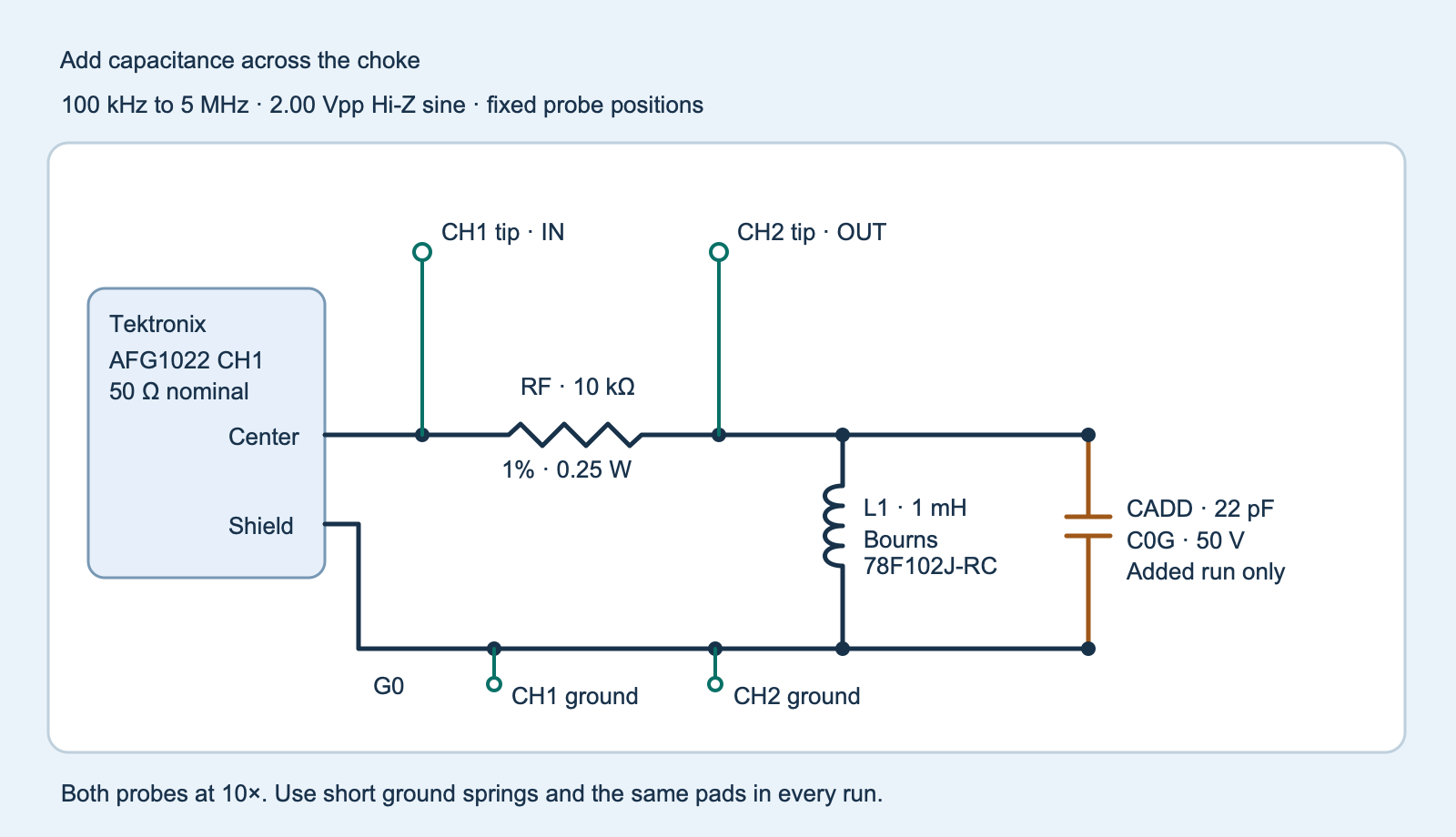
choke-resonance-fixture.svg).The 10 kΩ feed helps turn a change in the choke branch’s impedance into a voltage change. For an ideal 1 mH inductance, the magnitude of its reactance is 2π × 100 kHz × 1 mH ≈ 628 Ω at 100 kHz. The divider would show about 0.125 Vpp at OUT for 2.00 Vpp at IN. For a current scale, a short across OUT and G0 would draw about 1.00 V peak ÷ 10 kΩ, or 0.10 mA peak, if IN is 2.00 Vpp. This calculation sizes the feed resistor for a shorted output. The branch can contain circulating current near resonance, so it does not bound the coil current by itself. For another current scale, 1 V peak across the 23.1 pF upper tolerance value at 5 MHz gives about 0.73 mA peak in the added capacitor by 2πfCV. This is a separate branch estimate using an assumed OUT voltage. Use the small signal and short wiring throughout.
Repeat the same frequency grid
- Before the sweep, put both probe tips temporarily on IN at 100 kHz, 1 MHz and 5 MHz, with both ground springs on G0. Verify their amplitude readings agree over your intended ranges. Where possible repeat the same-node check on a lower-amplitude source setting for the CH2 ranges used on OUT. Return CH2 to OUT, restore 2.00 Vpp and leave the fixture wiring fixed. The probe compensation experiment explains why both probe adjustments matter.
- With the capacitor absent, sweep 100 kHz to 5 MHz. Fill the blank worksheet (ZIP:
observations-blank.csv) forbaseline. Read several stable cycles and record IN and OUT Vpp from the same acquisition. Avoid clipping and choose ranges that show each waveform clearly. The worksheet starts with extra points in the region where the peak might occur. Add equal frequency rows to all three runs if an initial sweep shows a narrow or ambiguous peak. - Disable the generator output and solder the 22 pF part across OUT and G0, with short leads. Repeat exactly the same grid as
added. Then disable output, remove the capacitor without moving the choke or probe tips, and repeat asbaseline_repeat. Check for solder bridges or changed leads before interpreting drift.
Use the same instruments, probe arrangement and nominal amplitude for every sweep. A source adjustment or ground-spring change can alter the apparent peak. The feed resistor and layout also have parasitics. The calculation at 100 kHz does not calibrate the feed path at 5 MHz. A scope has finite bandwidth and gain accuracy. The worksheet’s amplitude screen is a comparison setting. Choose it to cover the known measurement-chain uncertainty and the observed spread of repeated readings on the actual ranges.
Separate a sampled peak from a resolved shift
At each frequency compute the voltage ratio H = VOUT,pp ÷ VIN,pp. Normalizing to the measured input removes the need to assume the generator always delivers its displayed amplitude. A ratio near one can arise if the choke branch has high impedance relative to the feed resistor.
A simple planning model puts an effective capacitance in parallel with 1 mH. If that total were 15 pF before adding the capacitor, 1 ÷ (2π√LC) gives about 1.30 MHz. With 22 pF added, 37 pF gives about 0.83 MHz. These are calculated examples. The 15 pF is illustrative, and the real fixture can contain frequency-dependent loss and distributed capacitance. The two voltage peaks do not by themselves identify a winding capacitance. Coilcraft’s measurement note describes how an inductor’s measured self-resonance can depend on the instrument and fixture.
The program reports the largest sampled ratio for each run. It refuses a tied or edge maximum. It also requires the peak’s lower amplitude-ratio bound to exceed both edge upper bounds by more than 10%. Each input amplitude receives a chosen proportional bound plus 1 mV. The default 2% plus 1 mV is a starting comparison screen. Increase it if your measurement chain warrants a wider bound, and repeat the bench check if the required bound is outside the program’s 0.25–10% setting range.
Every sampled point whose upper ratio bound can reach the largest lower bound is a peak candidate. The program requires one contiguous candidate region away from the edges, then extends the region to its adjacent sampled frequencies. This guarded span describes the sampled curve and its grid. It does not certify a continuous peak between points. The initial and repeat baseline spans must overlap. A downward shift is reported only when the whole added span lies below their union. If the spans overlap, report the shift as unresolved and refine the grid around both peaks.
Challenge. The two baseline spans do not overlap. What should you try?
Check whether the choke leads, ground spring or solder pads moved when the capacitor was removed. Verify the IN and OUT probe readings again and repeat all three sweeps. A second baseline from a changed fixture cannot validate the capacitor comparison.
Run the complete sweep analyzer
Download the experiment ZIP (ZIP: experiment-tests-v1.zip) with the full-size and editable drawing, blank comma-separated values (CSV) worksheet, code and tests. Keep frequency in hertz and amplitudes in volts peak-to-peak. Run python3 choke_sweep.py observations.csv --amplitude-error-percent 2 after choosing the amplitude screen. The supplied tests use constructed curves. Use only your actual measurements in the worksheet.
Complete Python sweep analyzer
"""Compare measured voltage peaks of an inductor in one fixed fixture."""

import argparse
import csv
from dataclasses import dataclass
import json
import math
from pathlib import Path
import sys

FIELDS = ("run", "frequency_hz", "input_vpp", "output_vpp")
RUNS = ("baseline", "added", "baseline_repeat")
EPSILON = 1e-12


@dataclass(frozen=True)
class Point:
    frequency: float
    gain: float
    gain_low: float
    gain_high: float


def bounded(raw, low, high, name):
    try:
        value = float(raw)
    except (TypeError, ValueError):
        raise ValueError(f"{name}: enter a number") from None
    if not math.isfinite(value) or not low <= value <= high:
        raise ValueError(f"{name}: expected {low:g} to {high:g}")
    return value


def read_sweeps(stream, error):
    reader = csv.reader(stream, strict=True)
    if tuple(next(reader, ())) != FIELDS:
        raise ValueError("use the exact worksheet headings")
    sweeps = {run: [] for run in RUNS}
    for row in reader:
        if len(row) != len(FIELDS) or row[0] not in sweeps:
            raise ValueError(f"row {reader.line_num}: unexpected run or number of fields")
        run, raw_f, raw_vin, raw_vout = row
        try:
            f = bounded(raw_f, 100_000, 5_000_000, "frequency_hz")
            vin = bounded(raw_vin, 1.0, 3.0, "input_vpp")
            vout = bounded(raw_vout, .015, 3.0, "output_vpp")
            if sweeps[run] and f <= sweeps[run][-1].frequency:
                raise ValueError("frequencies must rise within each run")
            # Apply the user's gain screen to both displayed amplitudes.
            # The absolute term covers a small displayed-reading floor.
            vin_error = error * vin + .001
            vout_error = error * vout + .001
            low = (vout - vout_error) / (vin + vin_error)
            high = (vout + vout_error) / (vin - vin_error)
            if low > 1 + EPSILON:
                raise ValueError("ratio interval lies above one; check probing or channel labels")
            sweeps[run].append(Point(f, vout / vin, low, high))
        except ValueError as exc:
            raise ValueError(f"row {reader.line_num}: {exc}") from None

    grid = [point.frequency for point in sweeps["baseline"]]
    if not 11 <= len(grid) <= 200 or grid[0] != 100_000 or grid[-1] != 5_000_000:
        raise ValueError("each run needs 11–200 matched frequencies spanning 100 kHz to 5 MHz")
    if any([point.frequency for point in points] != grid for points in sweeps.values()):
        raise ValueError("repeat the identical frequency grid in all three runs")
    if any(right > 1.35 * left + EPSILON for left, right in zip(grid, grid[1:])):
        raise ValueError("adjacent frequency ratio exceeds 1.35; add the same points in every run")
    return sweeps


def peak(points):
    maximum = max(point.gain for point in points)
    winners = [i for i, point in enumerate(points) if abs(point.gain - maximum) <= EPSILON]
    value = {"status": None, "sampled_frequency_hz": None,
             "sampled_gain": maximum, "guarded_peak_span_hz": None}
    if len(winners) != 1:
        return dict(value, status="tied_sampled_maximum")
    index = winners[0]
    value["sampled_frequency_hz"] = points[index].frequency
    if index in (0, len(points) - 1):
        return dict(value, status="sampled_maximum_at_sweep_edge")
    top = points[index]
    if top.gain_low <= 1.10 * max(points[0].gain_high, points[-1].gain_high) + EPSILON:
        return dict(value, status="peak_not_clear_of_both_sweep_edges")
    best_lower = max(point.gain_low for point in points)
    possible = [i for i, point in enumerate(points) if point.gain_high >= best_lower - EPSILON]
    first, last = possible[0], possible[-1]
    if possible != list(range(first, last + 1)):
        return dict(value, status="separate_competing_peak_regions")
    # The edge margin above guarantees both neighboring indices exist.
    lower, upper = points[first - 1].frequency, points[last + 1].frequency
    return dict(value, status="interior_peak_sampled", guarded_peak_span_hz=[lower, upper])


def analyze(stream, amplitude_error_percent=2.0):
    error = bounded(amplitude_error_percent, .25, 10, "amplitude error percent") / 100
    sweeps = read_sweeps(stream, error)
    peaks = {run: peak(points) for run, points in sweeps.items()}
    spans = [peaks[run]["guarded_peak_span_hz"] for run in RUNS]
    result = {"amplitude_error_percent_each_channel": amplitude_error_percent,
              "additive_amplitude_error_vpp": .001, "peaks": peaks,
              "status": "one_or_more_peaks_unresolved", "baseline_union_hz": None,
              "downward_shift_interval_hz": None}
    if any(span is None for span in spans):
        return result
    baseline, added, repeat = spans
    union = [min(baseline[0], repeat[0]), max(baseline[1], repeat[1])]
    result["baseline_union_hz"] = union
    if max(baseline[0], repeat[0]) > min(baseline[1], repeat[1]):
        return dict(result, status="baseline_repeat_disagrees")
    if added[1] >= union[0]:
        return dict(result, status="no_separated_downward_shift")
    return dict(result, status="downward_shift_observed_on_grid",
                downward_shift_interval_hz=[union[0] - added[1], union[1] - added[0]])


def main():
    parser = argparse.ArgumentParser(description=__doc__)
    parser.add_argument("worksheet", type=Path)
    parser.add_argument("--amplitude-error-percent", type=float, default=2.0)
    options = parser.parse_args()
    try:
        if options.worksheet.stat().st_size > 100_000:
            raise ValueError("worksheet exceeds 100 kB")
        with options.worksheet.open(encoding="utf-8-sig", newline="") as stream:
            report = analyze(stream, options.amplitude_error_percent)
    except (OSError, ValueError, csv.Error) as error:
        print(f"Sweep rejected: {error}", file=sys.stderr)
        return 2
    print(json.dumps(report, indent=2, allow_nan=False))
    return 0


if __name__ == "__main__":
    raise SystemExit(main())
The inductor pulse experiment uses a different test to look at current-dependent inductance. This small-signal sweep changes the external capacitance and holds the rest of the fixture fixed.
References
- Bourns, 78F Series Conformal Coated RF Choke data sheet. See the exact 78F102J-RC row.
- KEMET, C315C220J5G5TA exact product sheet.
- Coilcraft, Measuring Self Resonant Frequency. See residual fixture effects.
- Tektronix, AFG1000 series specifications and performance verification.
- RIGOL, DHO800 series data sheet and PVP2350 probe guide.
Download the complete reader files (ZIP) for the original editable drawing, PNG, worksheet and code in bourns-78f-choke-fixture-resonance. The full main program is also included above.