A three-resistor attenuator and a single series resistor can give almost the same output voltage. The generator can still see a very different load. Build both networks, measure their input and output on the same oscilloscope, and use a through connection to estimate how much each network loads a 50 Ω source.
An attenuator pad is a passive circuit that reduces signal amplitude. A T pad uses two series resistors and one resistor from their junction to the return. The shape resembles the letter T. When its output is terminated in the design resistance, the correct resistor values also present that resistance at its input. This experiment tests the low-frequency resistive behavior with a 10 kHz sine wave.
Wire the pad and leave the termination in place
- Use two 16.5 Ω, one 66.5 Ω, and one 100 Ω resistor. Use 1%, 0.25 W metal-film parts. Mount the resistors and the input and output Bayonet Neill–Concelman (BNC) connectors on a small terminal fixture or soldered board. Join both BNC shells at the shared return G0. The center contacts are VIN and VOUT.
- For the T pad, connect one 16.5 Ω resistor from VIN to node M and the other from M to VOUT. Connect 66.5 Ω from M to G0. For the through control, remove all three resistors and connect a short wire from VIN to VOUT. For the series control, replace that wire with 100 Ω between VIN and VOUT. Use only one network at a time.
- Use channel 1 of a SIGLENT SDG1032X as the source. Use two short 50 Ω BNC cables, such as Pomona BNC-C-36. The first runs from the source to VIN. The second runs from VOUT to a Pomona 4119-50 feedthrough attached directly to channel 2 of a RIGOL DHO804. The feedthrough’s internal 50 Ω shunt connects center to shell while passing the voltage to the oscilloscope’s 1 MΩ input. It supplies the output termination in every loaded trial.
- Use a compensated RIGOL PVP2350 probe for oscilloscope channel 1, with the probe switch and scope channel set to 10×. Put its tip on VIN and its ground clip on G0. Set scope channel 2 to 1× for the direct coaxial cable. Use direct-current coupling on both channels. The cable shields and probe clip all meet the circuit return. Keep the instruments’ protective earth connections intact.
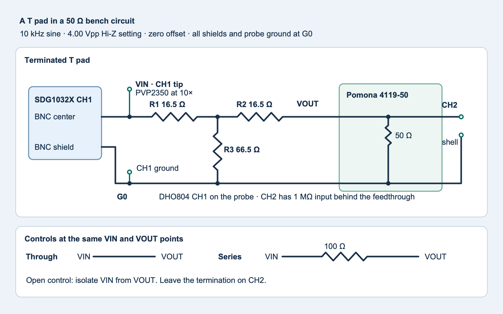
t-pad-fixture.svg) · Full-size PNG.Calculate the expected input and output
Let Z₀ be 50 Ω and K the matched input-to-output voltage ratio, with K = 106/20 ≈ 1.995. The midpoint sees the parallel combination P of the shunt resistor and the second series resistor plus the load. With equal series resistors R and a 50 Ω load, matching requires R + P = Z₀. The two voltage dividers then give VOUT ÷ VIN = (Z₀ − R) ÷ (Z₀ + R). Solving gives R = Z₀ × (K − 1) ÷ (K + 1). The shunt is R₃ = (Z₀² − R²) ÷ (2R). For 6 dB, the ideal values are about 16.61 Ω and 66.93 Ω. The fixture uses the nearby 1% values 16.5 Ω and 66.5 Ω.
Set the generator to a 10 kHz sine wave, 4.00 V peak-to-peak (Vpp), zero offset and Hi-Z load display. The Hi-Z setting describes the load the amplitude display assumes. The physical source resistance stays nominally 50 Ω. With the through wire and 50 Ω load, that source resistance divides 4.00 Vpp down to about 2.00 Vpp. The T pad’s input resistance is 16.5 Ω + (66.5 Ω ∥ 66.5 Ω) = 49.75 Ω with the same load. The series control presents 100 Ω + 50 Ω = 150 Ω, so the input rises to 3.00 Vpp. The output then falls to 1.00 Vpp across the 50 Ω portion of that network.
| Network | Input resistance | VIN | VOUT |
|---|---|---|---|
| Through wire | 50 Ω | 2.000 Vpp | 2.000 Vpp |
| T pad | 49.75 Ω | 1.995 Vpp | 1.003 Vpp |
| 100 Ω series | 150 Ω | 3.000 Vpp | 1.000 Vpp |
These are circuit calculations. They omit small probe and cable effects. The DHO804 1 MΩ input in parallel with 50 Ω changes the nominal termination by about 0.0025 Ω. The PVP2350 at 10× presents about 10 MΩ and 10 pF nominal. The reactance of 10 pF at 10 kHz is about 1.6 MΩ. Both probe impedances are much larger than the resistances under test. With a 2.00 V open peak and 50 Ω source, the available average sine-wave power is about 10 mW at a matched input. The 0.25 W resistors and 2 W terminator have margin at these settings.
Take three rounds with the same scope settings
- With generator output disabled, configure the through wire. Inspect center conductors, both shells and the probe’s ground connection. Verify that the scope carries the 4119-50 rather than the 75 Ω or 600 Ω version. Start with channel 1 at 1 V/div and channel 2 at 0.5 V/div. Trigger on the rising channel 1 waveform near 0 V and choose a time window with several cycles. Use the same two vertical scales, probe settings and scope acquisition for every reading.
- Begin a round with the open measurement. Turn the generator output off, then remove the network between VIN and VOUT. Isolate the termination from VIN. Channel 1 remains connected to VIN, with its ground on G0. Turn on the source and record the measured VIN peak-to-peak value as
open. Leave the output cell blank. - For
through, connect the short through wire with the generator off. Turn it on and record both peak-to-peak readings. The two channels observe the same signal through their different connections. A disagreement greater than 10% is a wiring or setting check, so verify channel factors, termination, waveform clipping and waveform frequency before proceeding. - Repeat for
t_padandseriesusing the same termination, cables and 4.00 Vpp generator setting. Turn the output off before each change. Record both scope readings once the waveform is stable. Repeat the complete round twice more. If the open readings drift or the measured through input sits close to the open voltage, inspect the connections and settings.
Use the blank worksheet (ZIP: observations-blank.csv) or download the experiment ZIP (ZIP: experiment-tests-v1.zip) with the original diagram, code and tests. Enter peak-to-peak volts in a copy of the worksheet. The analyzer uses the median of three readings per condition. It also reports each channel’s spread to help you see when one number hides an unstable reading.
Separate insertion loss from input loading
Insertion loss is the decrease in delivered signal when you replace the through wire with the network. With the same load, it is 20 × log₁₀(VOUTthrough ÷ VOUTnetwork) decibels. Both output measurements use the same channel. This is different from the loaded port voltage ratio VOUT ÷ VIN, which uses two channels and excludes the voltage already lost inside the source.
Estimate the source resistance from the open reading and the through wire. Let VOC be the open VIN and VTH the through VIN. Then Rsource = Rload × (VOC ÷ VTH − 1). With either network connected, Rin = Rsource × VIN ÷ (VOC − VIN). These estimates use channel 1 only, and assume that the source is stable and the loads are effectively resistive at 10 kHz. Peak-to-peak magnitude alone cannot determine a complex impedance. Use the through estimate as a check on the source model.
The analyzer uses nominal 50 Ω unless you pass a verified termination value from 49 to 51 Ω. It flags input sag smaller than 0.10 Vpp, because dividing by that small voltage difference makes the resistance estimate sensitive to small reading errors. Its 40–60 Ω source plausibility check and amplitude checks detect gross setup problems. The scope resolution, the 2% terminator tolerance and probe errors limit the precision. A result near 50 Ω shows the intended behavior within this setup. It does not certify an RF return-loss specification.
python3 tpad_compare.py observations.csv
python3 -B -m unittest -v test_tpad_compare.py
Complete Python worksheet analyzer
#!/usr/bin/env python3
"""Compare a resistive attenuator, a series resistor and a through connection."""

import argparse
import csv
import json
import math
from pathlib import Path
from statistics import median
import sys


CONFIGURATIONS = ("open", "through", "t_pad", "series")
TRIALS = ("1", "2", "3")
FIELDS = ("configuration", "trial", "input_vpp", "output_vpp")
EXPECTED_KEYS = {(kind, trial) for kind in CONFIGURATIONS for trial in TRIALS}
# Round-off allowance for calculated boundaries, below scope resolution.
COMPARISON_EPSILON = 1e-12


def bounded(raw, low, high, label):
    try:
        value = float(raw)
    except (TypeError, ValueError):
        raise ValueError(f"{label}: enter a number") from None
    if not math.isfinite(value) or not low <= value <= high:
        raise ValueError(f"{label}: expected {low:g} to {high:g}")
    return value


def parse_worksheet(stream):
    reader = csv.reader(stream, strict=True)
    if tuple(next(reader, ())) != FIELDS:
        raise ValueError("use the exact worksheet headings")
    readings = {}
    for line, row in enumerate(reader, 2):
        key = tuple(row[:2])
        if len(row) != len(FIELDS) or key not in EXPECTED_KEYS:
            raise ValueError(f"line {line}: invalid configuration, trial or column count")
        if key in readings:
            raise ValueError(f"line {line}: repeated trial {key}")
        input_vpp = bounded(row[2], 0.10, 4.50, f"line {line} input_vpp")
        if key[0] == "open":
            if row[3] != "":
                raise ValueError(f"line {line}: open output must be blank")
            readings[key] = (input_vpp, None)
            continue
        output_vpp = bounded(row[3], 0.10, 4.50, f"line {line} output_vpp")
        if key[0] == "through":
            if abs(input_vpp - output_vpp) > 0.10 * input_vpp + COMPARISON_EPSILON:
                raise ValueError(f"line {line}: through channels disagree by over 10%")
        elif output_vpp > 1.05 * input_vpp:
            raise ValueError(f"line {line}: output exceeds input in a passive circuit")
        readings[key] = (input_vpp, output_vpp)
    if readings.keys() != EXPECTED_KEYS:
        raise ValueError("need all twelve trials")
    return readings


def summarize(readings, kind):
    rows = [readings[kind, trial] for trial in TRIALS]
    inputs = [row[0] for row in rows]
    outputs = [row[1] for row in rows if row[1] is not None]
    result = {
        "input_vpp": median(inputs),
        "input_spread_vpp": max(inputs) - min(inputs),
    }
    if outputs:
        result["output_vpp"] = median(outputs)
        result["output_spread_vpp"] = max(outputs) - min(outputs)
    return result


def divider_factor(open_vpp, input_vpp):
    sag = open_vpp - input_vpp
    if sag < 0.10 - COMPARISON_EPSILON:
        raise ValueError("input sag below 0.10 Vpp, resistance estimate unresolved")
    return input_vpp / sag


def analyze(stream, load_ohms=50.0):
    load_ohms = bounded(load_ohms, 49, 51, "termination resistance in ohms")
    readings = parse_worksheet(stream)
    configurations = {
        kind: summarize(readings, kind) for kind in CONFIGURATIONS
    }
    open_vpp = configurations["open"]["input_vpp"]
    bounded(open_vpp, 3.60, 4.40, "open input Vpp")
    if configurations["open"]["input_spread_vpp"] > 0.10 + COMPARISON_EPSILON:
        raise ValueError("open input spread exceeds 0.10 Vpp, check source stability")
    through = configurations["through"]
    source_ohms = load_ohms / divider_factor(open_vpp, through["input_vpp"])
    bounded(source_ohms, 40 - COMPARISON_EPSILON, 60 + COMPARISON_EPSILON,
            "estimated source resistance in ohms")
    for kind in ("t_pad", "series"):
        item = configurations[kind]
        item["estimated_input_ohms"] = (
            source_ohms * divider_factor(open_vpp, item["input_vpp"])
        )
        item["insertion_loss_db"] = 20 * math.log10(
            through["output_vpp"] / item["output_vpp"]
        )
        item["loaded_port_voltage_ratio"] = item["output_vpp"] / item["input_vpp"]
    return {
        "assumed_termination_ohms": load_ohms,
        "estimated_source_ohms": source_ohms,
        "configurations": configurations,
    }


def main():
    parser = argparse.ArgumentParser(description=__doc__)
    parser.add_argument("worksheet", type=Path)
    parser.add_argument("--load-ohms", type=float, default=50.0)
    args = parser.parse_args()
    try:
        with args.worksheet.open(encoding="utf-8-sig", newline="") as stream:
            result = analyze(stream, args.load_ohms)
    except (OSError, ValueError, csv.Error) as error:
        print(f"Worksheet error: {error}", file=sys.stderr)
        return 2
    print(json.dumps(result, indent=2, allow_nan=False))
    return 0


if __name__ == "__main__":
    sys.exit(main())
Challenge. How can two 1 Vpp outputs hide different source loads?
One 1 Vpp output follows 2 Vpp at the input. The other follows 3 Vpp. With a 4 Vpp open source and 50 Ω source resistance, the input resistance is about 50 Ω for the first and 150 Ω for the second. The output voltage by itself gives no indication that the source delivered different current.
The coaxial cable round-trip experiment uses time separation to observe a reflection. The worksheet here measures settled amplitudes at low frequency. Its included Python tests use synthetic records.
Manufacturer references
- SIGLENT, SDG1032X generator and SDG1000X user manual, output load setting and fixed 50 Ω source.
- Pomona, 4119 feedthrough specifications and BNC-C-36 cable family.
- RIGOL, DHO800 data sheet and PVP2350 probe manual.
Download the complete reader files (ZIP) for the original editable drawing, PNG, worksheet and code in resistive-t-pad-source-loading. The full main program is also included above.