Drive a diode forward and then reverse the voltage. The diode can carry reverse current briefly as stored charge leaves its junction. Capture the current for two axial Vishay rectifiers, then shorten the forward pulse with the same pulse amplitude and acquisition settings. The two changes let you compare how the device and its recent conduction affect the measured transient.
This fixture gives a signed current trace and an integral over a stated time window. The published reverse recovery time is a switching measurement made at specified forward and reverse currents and a specified return level. Keep the two measurements distinct when you compare results.
Identify the rectifiers
Use Vishay General Semiconductor 1N4007-E3/54 and UF4007-E3/54. Both are single axial DO-41 (DO-204AL) rectifiers with a cathode band, a 1000 V repetitive peak reverse rating and a 1 A average forward rating under their data-sheet conditions. The parts share a package and voltage class. The 1N4007 is a general-purpose rectifier and its Vishay data sheet gives no reverse-recovery-time limit. The UF4007 data sheet gives 75 ns maximum at forward current 0.5 A, reverse current 1.0 A and a 0.25 A return criterion. Those currents are much higher than in this bench setup. The /54 order suffix identifies tape-and-reel packaging. Keep the source bag or reel label because the body marking alone may not establish the full order code.
The reverse current can also include junction displacement current, which flows when the electric field across the diode changes, and pickup from nearby changing voltages. The shunt measures the sum that reaches it. A bare fixture run helps reveal pickup without a diode, while a shorter forward pulse changes the charge history of an installed diode. The bare run also removes the diode’s junction capacitance, so its trace cannot be subtracted to isolate stored charge.
Build a compact grounded fixture
- With the generator output disabled, connect its channel 1 center conductor to DRIVE. Connect a 100 Ω, 1%, 0.5 W metal-film resistor from DRIVE to the diode anode. Fit the banded cathode at SHUNT. Connect a 10 Ω, 1%, 0.25 W metal-film resistor from SHUNT to G0. A shunt is a known resistor used to infer current from its voltage drop. Build on a small soldered board with a short return and the same lead spacing for both parts.
- Use a Tektronix AFG1022 for the pulse and a RIGOL DHO804 oscilloscope with two compensated PVP2350 probes at 10×. Set matching probe attenuation in the scope. Use direct-current (DC) coupling, high-impedance inputs and the scope’s full bandwidth. Put the CH1 scope tip on DRIVE and CH2 on SHUNT. Connect the generator shield and both short probe ground springs to G0 only. Keep protective earth in place and use no external power supply. A spring attached to the diode terminal would change the circuit.
- Select pulse mode at 1 kHz, with zero offset and 6.00 V peak-to-peak on the generator’s high-impedance (Hi-Z) display. Set a 100 µs high width for the long condition. On the bare fixture verify about +3.00 V high and −3.00 V low on DRIVE. Leave the 50 Ω termination off. The generator still has a nominal 50 Ω source impedance, and DRIVE moves when the diode draws current.
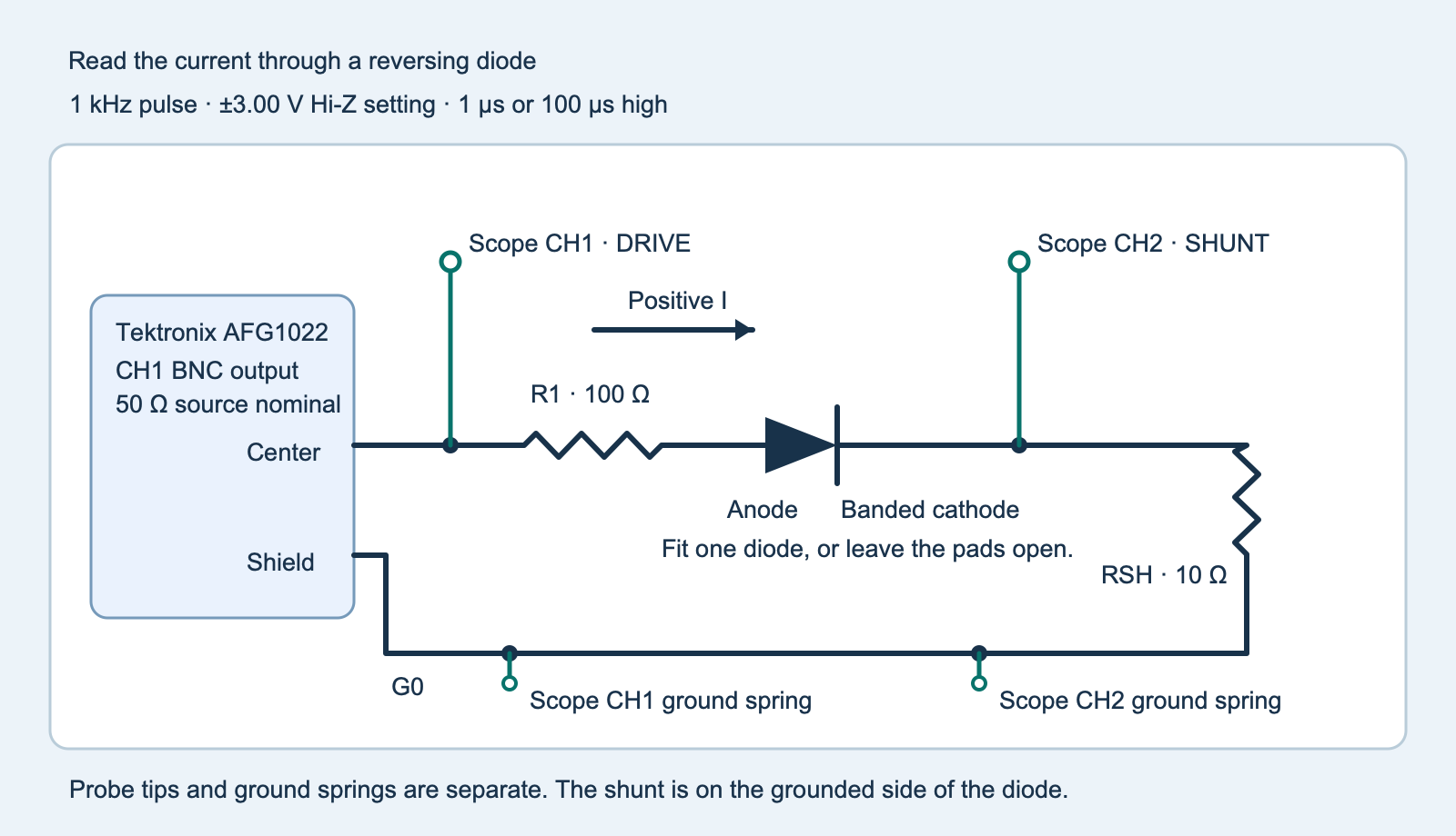
recovery-fixture.svg).For a planning estimate with a 0.70 V forward drop and 50 Ω source impedance, the forward current is (3.00 − 0.70) V ÷ (50 + 100 + 10) Ω = 14.4 mA. The shunt reads about +0.144 V. If the diode voltage were briefly still +0.70 V just after an ideal change to −3.00 V, the same model gives −23.1 mA and about 54 mW instantaneous in the 100 Ω resistor. Once the diode blocks, almost all the reverse voltage appears across it. These values describe a simple planning model. Read the actual waveforms for overshoot, ringing and the peak absolute current. Stop and check the generator display and wiring if the shunt exceeds ±0.40 V, equivalent to about 40 mA at 10 Ω.
Capture four loaded edges and one open edge
- Compensate both probes before the measurements. With the output disabled, touch the CH2 tip to G0 while retaining the same probe factor, input range and offset. Use automatic triggering for this grounded check. Save or note the median grounded reading in volts and the largest absolute deviation from that median. Return the tip to SHUNT. Choose a current floor above that noise after dividing by the shunt resistance. A 3 mV floor at 10 Ω is 0.30 mA. Check the grounded offset again after the run and repeat if it changes enough to affect your comparison.
- For each diode take a short capture at 1.00 µs high and a long capture at 100 µs high. Keep the frequency, amplitudes, probe placement, acquisition settings and low interval long enough for recovery. Use the same falling-edge trigger on DRIVE at 0 V. First view the whole pulse and verify the actual width and a stable low interval, then set the acquisition window to include about −0.9 µs through +45 µs around that edge. With both channels active, choose Storage → Save Wave and select Memory and comma-separated values (CSV). Crop a copy to the falling-edge window and retain the original export. Inspect both scope traces for clipping. Keep raw simultaneous samples, with no gap above 10 ns in the export. The time column must be in seconds relative to the scope trigger.
- Disable output before changing either part. Repeat with no diode in the same pads at the long width to capture the fixture’s pickup. Save each capture with the headers in the scope trace template (ZIP:
scope-trace-template.csv). Keep the three values on each common time row. Enter the captures, settings and observations in the blank worksheet (ZIP:observations-blank.csv). Take at least three complete sets if you want to compare repeatability.
The DHO804 has 70 MHz analog bandwidth. The AFG1022 specifies a typical fixed pulse edge shorter than 12 ns. Probe loading, the generator edge, the scope bandwidth and the exported sample gaps all affect a short transient. A long ground lead can produce ringing that looks like current. The probe compensation experiment shows one way to identify a changed scope response before attributing a short feature to the diode.
Integrate a fixed window
For each trace find the falling 0 V crossing on the measured DRIVE signal and call it t = 0. Compute I = (VSHUNT − Vzero) ÷ RSHUNT. Forward current is positive. For the signed negative-window charge, integrate min(I, 0) from 0 to 20 µs. The program joins adjacent samples by straight lines and splits any segment that crosses zero. A synthetic −10 mA triangle spanning 1.0 µs has area −5 nC. A current tail that continues past 20 µs contributes only its captured portion.
The analyzer looks for a reverse excursion containing at least four recorded samples below the negative floor and spanning at least 50 ns. A shorter excursion can still contribute to the area. The return bracket uses the last sample outside the ±floor and the first subsequent sample inside it, with at least 0.30 µs of quiet samples through the end of the window. It reports an unresolved bracket if the trace fails those conditions. It also suppresses a return bracket if the open fixture exceeds the same floor. An observed bracket includes the probe and scope response.
Compare each diode’s short and long captures first. The analyzer’s broad current and drive windows screen wiring and scaling. Compare the measured forward current, DRIVE high and late low voltages, and the reverse tail baseline across the four loaded captures. Within each diode use agreement to about 10% in forward current as an initial check. If a plateau or baseline changes materially, check the setup and repeat before attributing an area change to forward-pulse duration. Then compare the two devices at the same settings and record any difference in forward current. The 35–40 µs tail reading gives you a separate check for residual offset or a current tail. Small integrated areas are sensitive to baseline: a constant −1 mV shunt error at 10 Ω gives −2 nC over 20 µs. Compare small areas with the open capture, repeated measurements and this offset sensitivity. A negative area alone cannot identify its physical source.
Challenge. The fast trace has a small negative area and no return bracket. What can you report?
Report the signed area, peak, floor and open-fixture result for this capture. Check whether a repeat has the same shape above the open control and whether the time resolution supports the bracket. The manufacturer’s switching-time limit uses its own test conditions.
Run the complete analyzer
Download the experiment ZIP (ZIP: experiment-tests-v1.zip) with the program, host tests, editable circuit and blank worksheets. Save the five traces as std-short.csv, std-long.csv, fast-short.csv, fast-long.csv and open-long.csv. For example, if your grounded median was 1 mV, run python3 reverse_window.py std-short.csv std-long.csv fast-short.csv fast-long.csv open-long.csv --zero-v 0.001 --floor-ma 0.30. Substitute your own offset, floor and, if measured, the actual shunt with --shunt-ohms. The included host tests use synthetic waveforms. Enter your own bench readings in the worksheet.
Complete Python analyzer
"""Compare signed reverse-current windows from synchronized scope captures."""

import argparse
from bisect import bisect_left
import csv
from dataclasses import dataclass
import json
import math
from pathlib import Path
from statistics import median
import sys

HEADER = ("time_s", "drive_v", "shunt_v")
LABELS = ("standard_short", "standard_long", "fast_short", "fast_long", "open_long")
MAX_SAMPLE_GAP = 10e-9
SEARCH = 0.20e-6
WINDOW = 20e-6
MIN_REVERSE_SPAN = 50e-9
QUIET_HOLD = 0.30e-6
TIME_EPSILON = 1e-15
CURRENT_EPSILON_A = 1e-12


@dataclass(frozen=True)
class Sample:
    t: float
    drive: float
    shunt: float


def read_capture(path):
    if path.stat().st_size > 2_000_000:
        raise ValueError("crop capture to one falling edge, at most 2 MB")
    with path.open(encoding="utf-8-sig", newline="") as stream:
        rows = csv.reader(stream, strict=True)
        if tuple(next(rows, ())) != HEADER:
            raise ValueError("expected time_s,drive_v,shunt_v")
        samples = []
        for row in rows:
            if len(row) != len(HEADER):
                raise ValueError(f"row {rows.line_num}: expected three fields")
            try:
                sample = Sample(*(float(field) for field in row))
            except ValueError:
                raise ValueError(f"row {rows.line_num}: expected three numbers") from None
            if not all(math.isfinite(value) for value in (sample.t, sample.drive, sample.shunt)):
                raise ValueError(f"row {rows.line_num}: nonfinite value")
            if abs(sample.t) > 0.001 or abs(sample.drive) > 3.6 or abs(sample.shunt) > 0.40:
                raise ValueError(f"row {rows.line_num}: outside fixture time or voltage bounds")
            if samples and not 0 < sample.t - samples[-1].t <= MAX_SAMPLE_GAP + TIME_EPSILON:
                raise ValueError(f"row {rows.line_num}: timestamps must increase with gaps no larger than 10 ns")
            samples.append(sample)
    if len(samples) < 2:
        raise ValueError("no complete capture")
    return samples


def falling_zero(samples):
    edges = []
    for first, second in zip(samples, samples[1:]):
        if first.drive >= 0 > second.drive:
            t = first.t + first.drive * (second.t - first.t) / (first.drive - second.drive)
            if -SEARCH <= t <= SEARCH:
                edges.append(t)
    if len(edges) != 1:
        raise ValueError("need one falling drive zero crossing within ±0.20 µs of the trigger")
    return edges[0]


def window_points(times, currents, start, end):
    def interpolate(t):
        index = bisect_left(times, t)
        if times[index] == t:
            return currents[index]
        first, second = index - 1, index
        fraction = (t - times[first]) / (times[second] - times[first])
        return currents[first] + fraction * (currents[second] - currents[first])

    interior = [(t, i) for t, i in zip(times, currents) if start < t < end]
    return [(start, interpolate(start)), *interior, (end, interpolate(end))]


def reverse_integral(points):
    charge = 0.0
    for (t0, i0), (t1, i1) in zip(points, points[1:]):
        if max(i0, i1) <= 0:
            charge += (t1 - t0) * (i0 + i1) / 2
        elif min(i0, i1) < 0:
            negative = min(i0, i1)
            negative_fraction = -negative / abs(i1 - i0)
            charge += (t1 - t0) * negative_fraction * negative / 2
    return charge


def return_bracket(points, floor):
    cutoff = floor + CURRENT_EPSILON_A
    peak_index = min(range(len(points)), key=lambda n: points[n][1])
    if points[peak_index][1] >= -cutoff:
        return {"status": "no_reverse_peak_above_floor", "bracket_us": None}
    left = peak_index
    right = peak_index
    while left > 0 and points[left - 1][1] < -cutoff:
        left -= 1
    while right + 1 < len(points) and points[right + 1][1] < -cutoff:
        right += 1
    if right - left + 1 < 4 or points[right][0] - points[left][0] + TIME_EPSILON < MIN_REVERSE_SPAN:
        return {"status": "reverse_excursion_too_short_to_resolve", "bracket_us": None}
    last_outside = max(n for n in range(peak_index, len(points)) if abs(points[n][1]) > cutoff)
    first_quiet = last_outside + 1
    if first_quiet == len(points) or points[-1][0] - points[first_quiet][0] + TIME_EPSILON < QUIET_HOLD:
        return {"status": "quiet_return_not_observed_in_window", "bracket_us": None}
    return {"status": "quiet_return_bracketed",
            "bracket_us": [points[last_outside][0] * 1e6, points[first_quiet][0] * 1e6]}


def analyze(samples, shunt_ohms, zero_v, floor_ma, is_open):
    edge = falling_zero(samples)
    times = [sample.t - edge for sample in samples]
    if times[0] > -0.65e-6 or times[-1] < 40.10e-6:
        raise ValueError("capture at least 0.65 µs before and 40.10 µs after the falling edge")
    current = [(sample.shunt - zero_v) / shunt_ohms for sample in samples]
    before = [n for n, t in enumerate(times) if -0.60e-6 <= t <= -0.20e-6]
    late = [n for n, t in enumerate(times) if 35e-6 <= t <= 40e-6]
    drive_high = median(samples[n].drive for n in before)
    drive_low = median(samples[n].drive for n in late)
    if not 1.0 <= drive_high <= 3.5 or not -3.5 <= drive_low <= -1.0:
        raise ValueError("check ±3 V generator levels and scope attenuation")
    forward = median(current[n] for n in before)
    floor = floor_ma / 1000
    if is_open and abs(forward) > floor + CURRENT_EPSILON_A:
        raise ValueError("open fixture has a nonzero forward plateau; check offset or wiring")
    if not is_open and not 0.003 - CURRENT_EPSILON_A <= forward <= 0.030 + CURRENT_EPSILON_A:
        raise ValueError("expected 3–30 mA forward plateau; check diode polarity or shunt scale")

    points = window_points(times, current, 0.0, WINDOW)
    # Endpoints are interpolated for area only. Timing uses recorded samples.
    recorded = [(t, i) for t, i in zip(times, current) if 0 <= t <= WINDOW]
    signed_peak = min(0.0, min(i for _, i in points))
    return {
        "drive_crossing_input_time_us": edge * 1e6,
        "drive_high_v": drive_high,
        "drive_low_v": drive_low,
        "forward_plateau_ma": forward * 1000,
        "signed_reverse_peak_ma": signed_peak * 1000,
        "largest_absolute_window_current_ma": max(abs(i) for _, i in points) * 1000,
        "signed_negative_window_charge_nc": reverse_integral(points) * 1e9,
        "tail_median_current_ma": median(current[n] for n in late) * 1000,
        "return": None if is_open else return_bracket(recorded, floor),
    }


def main():
    parser = argparse.ArgumentParser(description=__doc__)
    for label in LABELS:
        parser.add_argument(label, type=Path)
    parser.add_argument("--shunt-ohms", type=float, default=10.0)
    parser.add_argument("--zero-v", type=float, required=True)
    parser.add_argument("--floor-ma", type=float, default=0.30)
    options = parser.parse_args()
    if not 9.90 <= options.shunt_ohms <= 10.10:
        parser.error("shunt value must be 9.90–10.10 Ω")
    if not -0.010 <= options.zero_v <= 0.010:
        parser.error("grounded shunt offset must be within ±0.010 V")
    if not 0.10 <= options.floor_ma <= 2.0:
        parser.error("choose a positive 0.10–2.00 mA floor above measured noise")
    captures = {}
    for label in LABELS:
        try:
            samples = read_capture(getattr(options, label))
            captures[label] = analyze(samples, options.shunt_ohms, options.zero_v,
                                      options.floor_ma, label == "open_long")
        except (OSError, ValueError, csv.Error) as error:
            print(f"{label}: {error}", file=sys.stderr)
            return 2
    control_peak = captures["open_long"]["largest_absolute_window_current_ma"]
    quiet_control = control_peak <= options.floor_ma + CURRENT_EPSILON_A * 1000
    for label, capture in captures.items():
        if label != "open_long" and not quiet_control and capture["return"]["bracket_us"] is not None:
            capture["return"] = {"status": "open_fixture_exceeded_floor", "bracket_us": None}
    report = {
        "signed_charge_window_us": [0, 20],
        "shunt_ohms": options.shunt_ohms,
        "grounded_shunt_zero_v": options.zero_v,
        "floor_ma": options.floor_ma,
        "open_fixture_within_floor": quiet_control,
        "captures": captures,
    }
    print(json.dumps(report, indent=2, allow_nan=False))
    return 0


if __name__ == "__main__":
    raise SystemExit(main())
For a separate direct-current diode measurement, see the 1N4148 forward-voltage temperature experiment. It measures voltage during forward conduction, where the recovery transient is outside the experiment.
References
- Vishay General Semiconductor, 1N4001–1N4007, document 88503, and the exact 1N4007 order-code list.
- Vishay General Semiconductor, UF4001–UF4007, document 88755. See the UF4007 switching test conditions and exact ordering table.
- Tektronix, AFG1000 series specifications and performance verification. See AFG1022 pulse and output characteristics.
- RIGOL, DHO800 series data sheet, DHO800 Save Wave user guide and PVP2350 probe guide.
Download the complete reader files (ZIP) for the original editable drawing, PNG, worksheet and code in rectifier-reverse-current-window. The full main program is also included above.