Press a hinged switch lever, then let it return. At one point on the way down the common terminal changes contacts. On the way back it can change at a different position. Record both contact voltages and the pusher position on the same oscilloscope time base. The three traces let you put bounds on the difference without assuming the audible click and the electrical transfer happen at the same instant.
Identify the switch and its operating limits
Use the Omron D2F-01L with a flat hinge lever, gold-alloy micro-load contacts, and straight terminals for a printed circuit board (PCB). The extra F in D2F-01FL selects a lower-force version. L2 identifies a roller lever. The plain D2F-L is the general-load model and has a different contact-load recommendation. Confirm the full part number from the original packaging and identify the terminals using the diagram on the manufacturer’s datasheet.
The switch has a common terminal (COM), a normally closed terminal (NC), and a normally open terminal (NO). Normally describes the lever at rest. A spring mechanism transfers COM from NC to NO as the lever passes the operating position. On the return stroke COM changes back at the releasing position. The manufacturer calls the travel between those two positions the movement differential (MD).
| D2F-01L specification | Value and use |
|---|---|
| Operating force | 0.78 newton (N) maximum at the indicated lever point. |
| Releasing force | 0.05 N minimum. |
| Operating position (OP) | 6.8 ± 1.5 millimeters (mm) relative to the datum in the hinge-lever drawing. |
| Free position (FP) | 10 mm maximum at the same drawing datum. |
| Overtravel (OT) | 0.55 mm minimum from the operating position toward the total travel position. |
| Movement differential | 0.5 mm maximum for the specified lever and direction. |
| Permissible lever speed | 5–500 mm/s. Use a continuous stroke across each transition. |
| Micro-load reference | 1 mA at 5 V direct current (DC). Use the manufacturer’s operating-range plot as well as this reference point. |
OP and FP are drawing heights. This experiment uses pusher displacement increasing down from a convenient local zero. The comparison uses differences on that local axis. A fixture offset, lever contact point, contact settling rule, or mechanical deflection can change the result, so use the table to set the experiment’s operating conditions and interpret your capture as a bench measurement.
Wire the three measurements
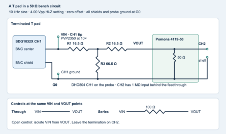
Use an isolated, current-limited low-voltage supply set to 5.20 V. Measure the actual rail and proceed from 5.10 to 5.30 V. Use two 2.2 kΩ, 1%, quarter-watt resistors as pull-ups, which bring an open contact node to the supply voltage. Connect one resistor from the positive rail to NC, and the other from the positive rail to NO. Connect COM to the circuit’s 0 V. Take the traces at NC on oscilloscope channel 1 (CH1) and NO on channel 2 (CH2).
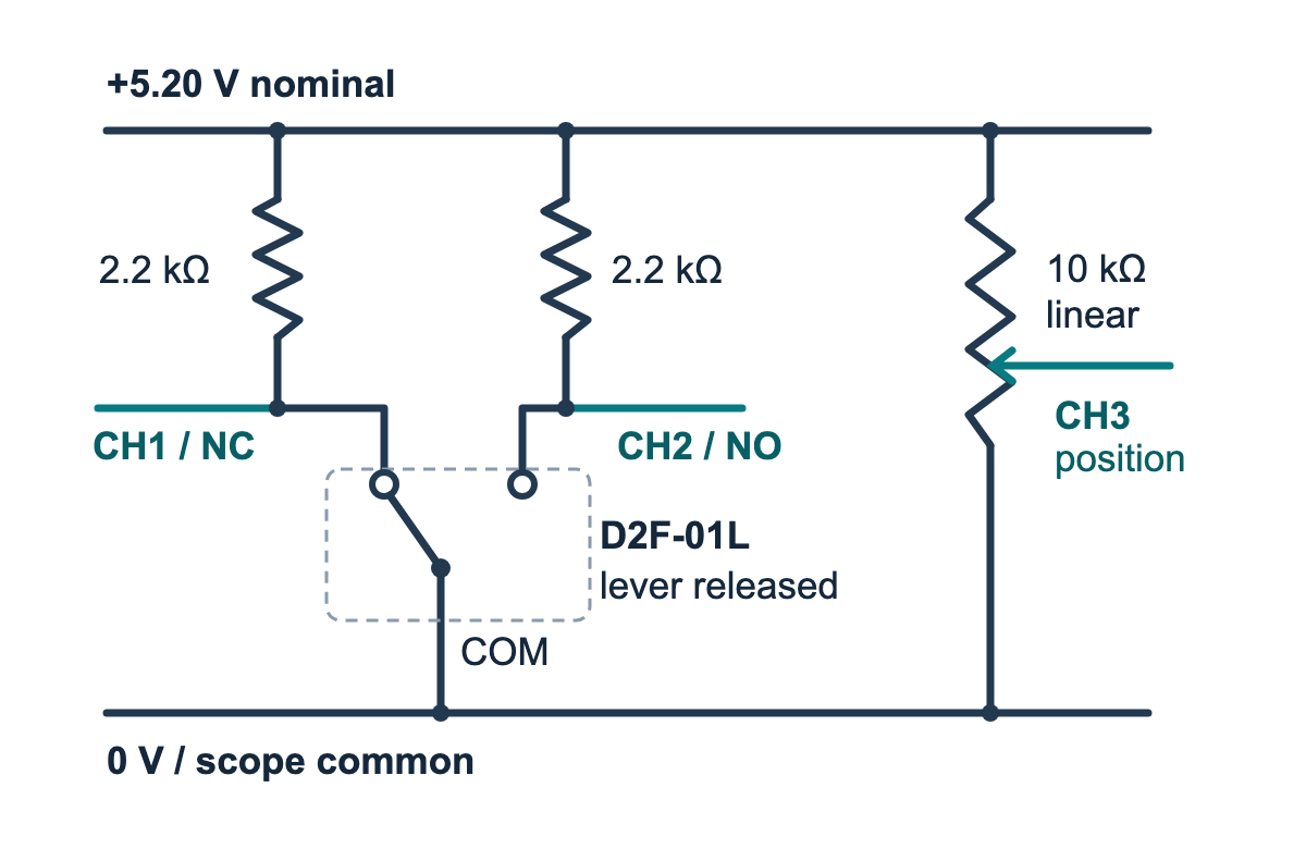
contact-fixture.svg).At 5.20 V and 2.2 kΩ, a closed contact carries about 2.36 mA. With the stated rail and resistor tolerances, it carries about 2.30–2.43 mA when the closed-node voltage is near zero. At the 0.20 V low threshold the lower bound is still 2.20 mA. The worst-case resistor dissipation is about 12.9 mW. Both resistors remain in circuit throughout. Use DC coupling and high-impedance inputs. Put every scope ground clip on the same 0 V node. A line-powered scope can reference those clips to earth, so keep the fixture on its isolated low-voltage supply and connect no mains circuit.
| Settled lever state | NC trace | NO trace |
|---|---|---|
| Released | Low | High |
| Pressed | High | Low |
For the analyzer, low means at most 0.20 V and high means at least the measured positive rail minus 0.20 V. The analyzer rejects readings more than 0.20 V outside the nominal ground-to-rail span. A complementary pair identifies each state. Any other pair is unclear. This allows the contacts to spend some sampled time between stable states without inventing a transfer position for that part of the trace.
Measure where the pusher is
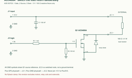
Clamp the body to a rigid base. Bring a rounded insulating pusher down along a guided slide at the point and direction marked A in the Omron hinge-lever drawing. Keep that point, the guide and the switch mounting fixed for all runs. Add a hard stop on the slide so the guide takes the end load. Leave clearance at the released end so the lever can return freely. Keep the pusher free of sideways load.
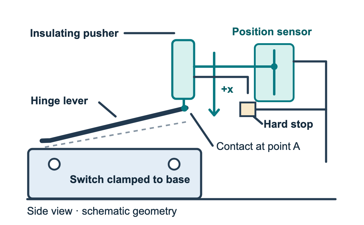
lever-fixture.svg).Couple a 10 kΩ linear position potentiometer directly to the carriage in parallel with the pusher’s direction. Choose a travel range that leaves margin at both ends and a coupling that moves freely with no lost motion on reversal. Connect the ends to the supply and 0 V, and measure the wiper on channel 3 (CH3). The potentiometer changes the voltage as the carriage moves. Set CH3 to resolve small changes around its working voltage, using DC offset if your scope supports it.
- Calibrate the carriage with the switch removed or mechanically clear. Use a dial indicator or another suitable displacement reference. Use the same supply, scope probes, attenuation and vertical settings planned for capture.
- Record scope voltages Va and Vb at two measured positions xa and xb that enclose the full captured stroke. Set xa below xb. The scope voltage may increase or decrease.
- Check at least three intermediate positions in both directions. Convert each voltage to position with the expression below. Use a conservative per-endpoint allowance u that covers the displacement reference’s uncertainty, the observed calibration residual, repeatability and scope voltage noise converted to position. Improve the fixture or measurement resolution if the resulting allowance exceeds 0.05 mm.
- Reinstall the switch without shifting the guide, potentiometer or reference. Confirm the two contact states at the ends of the eventual working stroke before recording a complete pair.
x = xa + (V − Va) × (xb − xa) / (Vb − Va).
Locate the first transfer with short trial strokes. Start with a stop setting short of transfer. Increase the stop in measured increments of at most 0.05 mm until a continuous pass changes both channels. Release between trial strokes. Stop and inspect alignment if the lever binds or reaches its internal stop. For the repeatable fixture, use the captured operating interval to set and check the external stop. Use 0.39–0.49 mm beyond the operating position as the fixture’s target. This sits inside the manufacturer’s general recommendation of 70–100% of overtravel, using the listed 0.55 mm minimum as the planning value. Compare that band with the full uncertainty range from the stop measurement and the press bracket. Keep the entire range in the band and stop the carriage with the external stop.
Capture the press and the release
- Set the sample rate to 10,000 samples per second or higher for the exported file. Capture all three channels at the same timestamps. Some oscilloscopes reduce the data exported, so check the actual CSV time increment. Use the individual readings and keep the acquisition and export settings consistent in both directions.
- Start the press capture in the released state. Move the carriage continuously in the positive direction across the transfer. Aim for about 10–20 mm/s near the transfer. Finish with both channels in the pressed state and record at least 2 ms of motion on either side of the transition. Use the external stop at the pressed end and return promptly.
- Record the release with the same fixture, axis and supply. Start in the pressed state and move continuously back through transfer until both channels settle released. Retain at least 2 ms of motion before and after the transition. The lever should return freely.
- Repeat at least three press/release pairs. Compare their intervals and the position slopes, and look for a calibration shift or changing contact point if the pairs disagree. Keep the raw scope captures for every accepted pair.
Save each three-channel capture as a comma-separated values (CSV) file with four columns named t_s,position_v,nc_v,no_v. Use seconds and volts. Copy the matching time row and all three voltages together. Remove manufacturer header rows and metadata. Use the oscilloscope’s common timestamps for all channels.
Calculate an interval for the difference
The program uses a pair of complementary contact voltages sustained across at least 1 ms of sampled data to qualify a stable run. It brackets the transfer between the last sample in the previous stable run and the first sample in the next stable run. A short ambiguous period or glitch expands the bracket when it separates those runs. The program uses the same increasing position coordinate on both strokes, expands each bracket by the user’s per-endpoint allowance u, and reports the difference interval:
difference ∈ [presslow − releasehigh, presshigh − releaselow].
For a synthetic arithmetic example, a press bracket of 0.60–0.63 mm, release bracket of 0.33–0.36 mm and u of 0.01 mm give expanded intervals of 0.59–0.64 mm and 0.32–0.37 mm. The difference is 0.22–0.32 mm. A stop read as 1.05 mm with its own 0.01 mm allowance gives an overtravel interval from (1.05 − 0.01) − 0.64 to (1.05 + 0.01) − 0.59, or 0.40–0.47 mm. If a measured difference interval includes zero, the capture does not resolve a positive separation.
The before, through and after speeds are measured slopes from the position trace, including flanks of at least 2 ms. A nonqualifying slope, timestamp gap over 0.2 ms, raw bracket over 0.10 mm or settled reversal rejects the capture. These are checks on sampled fixture motion. Inspect the position trace for smooth continuous motion through transfer when preparing the input files.
Run the complete analyzer
Save the program as lever_travel.py. This command shows the input format with example calibration numbers. Substitute your measured positions, voltages, rail and allowance.
python3 lever_travel.py press.csv release.csv --cal-a 0 2.00 --cal-b 1.20 2.60 --rail-v 5.20 --position-u-mm 0.01
#!/usr/bin/env python3
"""Bracket two settled contact transfers from synchronized scope CSV files."""

import argparse
import csv
from dataclasses import dataclass
from decimal import Decimal, DecimalException, InvalidOperation
import json
from pathlib import Path
import sys


D = Decimal
COLUMNS = ("t_s", "position_v", "nc_v", "no_v")
MAX_GAP_S = D("0.0002")
SETTLE_S = D("0.001")
SPEED_WINDOW_S = D("0.002")
MAX_RAW_BRACKET_MM = D("0.10")
MIN_SPEED_MM_S = D("5")
MAX_SPEED_MM_S = D("500")


@dataclass(frozen=True)
class Sample:
    t: Decimal
    x: Decimal
    state: str


def number(raw):
    try:
        value = D(raw)
    except (InvalidOperation, TypeError, ValueError) as exc:
        raise ValueError(f"not a decimal number: {raw!r}") from exc
    if not value.is_finite():
        raise ValueError(f"non-finite number: {raw!r}")
    return value


def contact_state(nc, no, rail):
    if min(nc, no) < D("-0.2") or max(nc, no) > rail + D("0.2"):
        raise ValueError("contact trace falls outside the measured rail allowance")
    low = D("0.2")
    high = rail - low
    if nc <= low and no >= high:
        return "released"
    if no <= low and nc >= high:
        return "pressed"
    return "unclear"


def read_samples(path, calibration, rail):
    xa, va, xb, vb = calibration
    if xa >= xb or va == vb:
        raise ValueError("calibration needs increasing displacement and distinct voltages")
    result = []
    with path.open(newline="", encoding="utf-8-sig") as source:
        rows = csv.DictReader(source, strict=True)
        if tuple(rows.fieldnames or ()) != COLUMNS:
            raise ValueError(f"{path}: expected columns {','.join(COLUMNS)}")
        for line, row in enumerate(rows, start=2):
            try:
                if None in row:
                    raise ValueError("unexpected extra field")
                t, v, nc, no = (number(row[name]) for name in COLUMNS)
                if result and not 0 < t - result[-1].t <= MAX_GAP_S:
                    raise ValueError("timestamps must rise, with steps no larger than 0.0002 s")
                x = xa + (v - va) * (xb - xa) / (vb - va)
                if not xa <= x <= xb:
                    raise ValueError("position outside the measured calibration span")
                result.append(Sample(t, x, contact_state(nc, no, rail)))
            except ValueError as exc:
                raise ValueError(f"{path}:{line}: {exc}") from exc
    if not result:
        raise ValueError(f"{path}: no samples")
    return result


def settled_runs(samples):
    runs = []
    first = 0
    for end in range(1, len(samples) + 1):
        state = samples[first].state
        if end < len(samples) and samples[end].state == state:
            continue
        last = end - 1
        if state != "unclear" and samples[last].t - samples[first].t >= SETTLE_S:
            runs.append((first, last, state))
        first = end
    return runs


def speed_at(samples, index, direction, flank):
    edge = samples[index]
    step = -1 if flank == "before" else 1
    other_index = index + step
    while 0 <= other_index < len(samples):
        other = samples[other_index]
        if abs(other.t - edge.t) >= SPEED_WINDOW_S:
            velocity = direction * (other.x - edge.x) / (other.t - edge.t)
            if not MIN_SPEED_MM_S <= velocity <= MAX_SPEED_MM_S:
                raise ValueError(f"{flank} transfer: {velocity:.3f} mm/s is outside 5–500")
            return velocity
        other_index += step
    raise ValueError(f"capture needs at least 2 ms of motion {flank} the transfer")


def bracket(samples, pressing, allowance):
    start, end = ("released", "pressed") if pressing else ("pressed", "released")
    direction = 1 if pressing else -1
    runs = settled_runs(samples)
    if not runs or runs[0][0] != 0 or runs[0][2] != start:
        raise ValueError(f"capture must start with a settled {start} state")
    if runs[-1][1] != len(samples) - 1 or runs[-1][2] != end:
        raise ValueError(f"capture must end with a settled {end} state")
    first_target = next(i for i, run in enumerate(runs) if run[2] == end)
    if any(run[2] != end for run in runs[first_target:]):
        raise ValueError("a settled state reverses after transfer")
    left = runs[first_target - 1][1]
    right = runs[first_target][0]
    # Reject a visible reversal near the transition even if mean speed passes.
    window = [s for s in samples
              if samples[left].t - SPEED_WINDOW_S <= s.t <= samples[right].t + SPEED_WINDOW_S]
    progress = direction * window[0].x
    for point in window:
        position = direction * point.x
        if position < progress - allowance:
            raise ValueError("position trace reverses near the transfer")
        progress = max(progress, position)

    first, last = samples[left], samples[right]
    raw_width = direction * (last.x - first.x)
    if not 0 < raw_width <= MAX_RAW_BRACKET_MM:
        raise ValueError("transfer bracket must have forward travel no wider than 0.10 mm")
    mean = raw_width / (last.t - first.t)
    if not MIN_SPEED_MM_S <= mean <= MAX_SPEED_MM_S:
        raise ValueError(f"mean through transfer: {mean:.3f} mm/s is outside 5–500")
    before = speed_at(samples, left, direction, "before")
    after = speed_at(samples, right, direction, "after")
    lo, hi = sorted((first.x, last.x))
    return (lo - allowance, hi + allowance), (lo, hi), (before, mean, after)


def summarize(press, release, calibration, rail, allowance):
    if not D("5.10") <= rail <= D("5.30"):
        raise ValueError("measure and enter a fixture rail between 5.10 and 5.30 V")
    if not 0 < allowance <= D("0.05"):
        raise ValueError("position allowance must be greater than 0 and at most 0.05 mm")
    press_interval, press_raw, press_speed = bracket(
        read_samples(press, calibration, rail), True, allowance)
    release_interval, release_raw, release_speed = bracket(
        read_samples(release, calibration, rail), False, allowance)
    travel = (press_interval[0] - release_interval[1],
              press_interval[1] - release_interval[0])
    return {
        "press_raw_mm": list(map(str, press_raw)),
        "release_raw_mm": list(map(str, release_raw)),
        "press_interval_mm": list(map(str, press_interval)),
        "release_interval_mm": list(map(str, release_interval)),
        "difference_interval_mm": list(map(str, travel)),
        "press_speed_mm_s_before_through_after": [f"{v:.3f}" for v in press_speed],
        "release_speed_mm_s_before_through_after": [f"{v:.3f}" for v in release_speed],
        "positive_difference_resolved": travel[0] > 0,
        "scope": "Electrical settled-transfer travel in this fixture. No datasheet conformance test."
    }


def main():
    parser = argparse.ArgumentParser(description=__doc__)
    parser.add_argument("press_csv", type=Path)
    parser.add_argument("release_csv", type=Path)
    parser.add_argument("--cal-a", nargs=2, type=number, required=True, metavar=("MM", "V"))
    parser.add_argument("--cal-b", nargs=2, type=number, required=True, metavar=("MM", "V"))
    parser.add_argument("--rail-v", type=number, required=True)
    parser.add_argument("--position-u-mm", type=number, required=True)
    args = parser.parse_args()
    try:
        report = summarize(args.press_csv, args.release_csv, (*args.cal_a, *args.cal_b),
                           args.rail_v, args.position_u_mm)
    except (OSError, ValueError, csv.Error, DecimalException) as exc:
        print(f"Capture rejected: {exc}", file=sys.stderr)
        return 2
    print(json.dumps(report, indent=2))
    return 0


if __name__ == "__main__":
    raise SystemExit(main())
Record the two raw and expanded intervals, the measured motion slopes and the difference for each pair. For a further experiment, compare captures at two repeatable speeds within the operating range while leaving the lever contact point and stop fixed. Inspect how the width of the electrical brackets changes before attributing any displacement shift to the switch. The supplied program tests use synthetic input data. Bench readings belong in your worksheet.
Challenge
One press interval is 0.41–0.46 mm and the matching release interval is 0.39–0.43 mm. Does the capture resolve a positive separation?
Answer
The possible difference runs from 0.41 − 0.43 = −0.02 mm to 0.46 − 0.39 = 0.07 mm. Zero lies inside the interval, so a positive separation is unresolved. Check the time spacing of the exported samples and the position calibration before repeating the pair.
Downloads and primary sources
- Editable diagrams, analyzer, host tests and blank worksheet (ZIP:
experiment-tests-v1.zip). - Omron D2F datasheet. Use the model list, contact form and ratings, hinge-lever drawing, and micro-load operating range.
- Omron general precautions for basic switches. See operating stroke, switch speed, and installation.
- Related lab on reed switch gap hysteresis. The magnetic switch fixture compares open and closed positions along a different motion axis.
Download the complete reader files (ZIP) for the original editable drawing, PNG, worksheet and code in d2f-01l-lever-transfer-travel. The full main program is also included above.