A bridge can show a voltage even when its sensor has stayed at the same resistance. Build a quarter Wheatstone bridge with an ordinary resistor standing in for a sensor. Add two known resistances to stand in for long leads, then move the voltmeter’s sense point to see how a three-wire connection changes the offset.
A Wheatstone bridge is two voltage dividers that share an excitation voltage. The output is the difference between their midpoints. In a quarter bridge, one of the four resistors represents the active sensor. This fixture changes that resistor by a known 10 Ω step so you can distinguish the response to the sensor from the shift caused by wiring.
Build one bridge with three accessible sense points
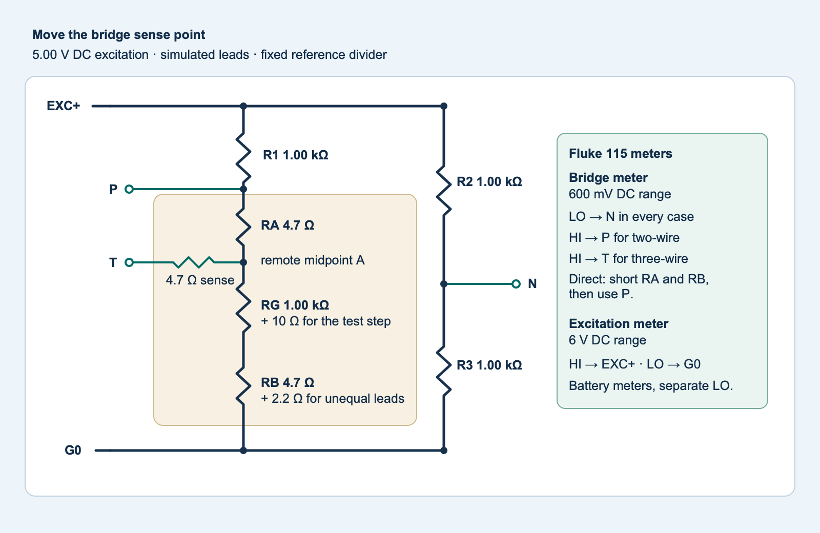
- Use four 1.00 kΩ, 0.1%, 0.25 W resistors for R1, RG, R2 and R3. R1 is the fixed upper arm. RG is the lower sensor stand-in. R2 and R3 are the fixed reference divider. Use three 4.7 Ω, 1%, 0.25 W resistors for the two force-lead models and the third sense-lead model. Keep a 2.2 Ω, 1% resistor for the unequal-lead condition and a 10 Ω, 1% resistor for the sensor step.
- Set channel 1 of a SIGLENT SPD3303X bench supply to 5.00 V direct current (DC) and a 20 mA current limit in independent mode. Its positive terminal is EXC+ and negative is G0. Leave the other supply outputs disconnected. The bridge draws about 5 mA at nominal values. Turn the output off whenever you move a clip or change a series resistor.
- Wire the active branch from EXC+ through R1 to P, then through RA to remote midpoint A, through RG and then through RB to G0. RA and RB start as 4.7 Ω. Connect the separate sense resistor from A to pad T. In the other branch, connect EXC+ through R2 to N, then through R3 to G0.
- Use two battery-operated Fluke 115 digital multimeters. Set the bridge meter to the 600.0 mV DC range and connect its black lead to N. Move its red lead between P and T as described below. Set the other meter to the 6.000 V DC range and connect red to EXC+ and black to G0. Keep both meters floating. Joining their black leads would tie the reference midpoint to G0 and change the bridge.
bridge-fixture.svg) · Full-size PNG.Predict what moving the clip will change
For an upper resistance U and a lower resistance L, the midpoint voltage is VEXC × L ÷ (U + L). Subtract the reference midpoint, nominally VEXC ÷ 2, to obtain the bridge reading. P and A are different places on the same current path.
| Condition | Active U | Active L at base | Base | With 10 Ω step |
|---|---|---|---|---|
| Direct, P | 1000 Ω | 1000 Ω | 0.00 mV | 12.44 mV |
| Two-wire, P | 1000 Ω | 1009.4 Ω | 11.70 mV | 24.02 mV |
| Three-wire, T | 1004.7 Ω | 1004.7 Ω | 0.00 mV | 12.38 mV |
| Unequal, T | 1004.7 Ω | 1006.9 Ω | 2.73 mV | 15.09 mV |
At P, both force-lead drops are below the red clip, so both resistances add to the lower arm. At T, the meter reads the remote midpoint through its own sense lead. One force-lead resistor is now above the sensed midpoint and the other is below. With equal force leads and equal nominal bridge resistors, their voltage drops cancel in the zero reading. With unequal leads, the remaining offset depends on their difference. The sense resistor carries only the small voltmeter current. The bridge output sees a source resistance of roughly 1 kΩ, including the two dividers and the sense resistor. A 10 MΩ meter therefore changes the differential voltage by roughly 0.01% in this fixture.
Measure the offset and the sensor step separately
- With the source off, temporarily short RA and RB and put the red bridge clip on P. Leave the reference connection on N. Power the bridge and check the excitation. Record
direct,basewith the signed bridge millivolts and actual excitation volts. Small residual offset can come from the four resistor tolerances and meter offset. - Power off, insert the 10 Ω resistor in series with RG and repeat the measurement as
direct,plus10. This resistor changes the sensor stand-in’s resistance without changing either lead. Remove it before starting the next base measurement. - Remove the two shorts so RA and RB are back in the force path. Keep the red bridge clip on P. Record
two_wire,baseandtwo_wire,plus10, again inserting 10 Ω only for the second observation. - Keep RA and RB at 4.7 Ω each and move the red bridge clip to T with power off. Record
three_wire,baseandthree_wire,plus10. Finally, add 2.2 Ω in series with RB alone and repeat both measurements asunequal. The three-wire sense path from A to T stays in place.
Use voltage regulation for all readings and accept excitation from 4.90 V to 5.10 V. Pause for the display to settle after each power change. If the output changes sign unexpectedly, verify red is at P or T and black is at N. Preserve a small negative offset if it is repeatable. If it is unclear where the bridge starts to differ, return to the direct condition and check the four resistor values. Verify that the bridge meter references N and the excitation meter references G0, with the two nodes kept separate.
Normalize the bridge readings
Copy the blank worksheet (ZIP: observations-blank.csv) and enter the measured excitation in volts and bridge output in millivolts, including the sign. Download the ZIP with the editable diagram, complete program and tests (ZIP: experiment-tests-v1.zip). Run python3 bridge_leads.py observations.csv. The analyzer divides output by the actual excitation so that the result is in millivolts per volt. It reports each wiring condition’s sensor response as the 10 Ω result minus the base result. It also reports base offset changes across the wiring conditions.
For Fluke 115 meters within one year of calibration at 18–28 °C and 0–90% relative humidity, the voltage accuracy used here is ±(0.5% of the reading + 2 counts). One count is 0.1 mV on the bridge meter and 1 mV on the excitation meter. The code evaluates each ratio at the four combinations of meter bounds, then carries the low and high limits into each subtraction. The bounds cover meter specification, with resistor mismatch and drift left as separate influences. If a difference interval includes zero, the meter readings do not resolve a nonzero difference under that model.
Compare the large two-wire base offset with the smaller equal-lead three-wire offset and the return of an offset when you add 2.2 Ω to RB. The lead resistance still changes the slope of the bridge response. The predicted equal-lead step is only about 0.06 mV smaller than the direct step at 5 V, below the display count of this setup. The experiment does not measure that small difference, calibrate strain, or compensate for the temperature of a real sensor.
Complete Python worksheet analyzer
#!/usr/bin/env python3
"""Compare two- and three-wire quarter-bridge measurements."""

import argparse
import csv
import json
import math
from pathlib import Path
import sys


FIELDS = ("wiring", "sensor", "excitation_v", "bridge_mv")
WIRINGS = ("direct", "two_wire", "three_wire", "unequal")
SENSOR_STATES = ("base", "plus10")
EXPECTED = {(wiring, sensor) for wiring in WIRINGS for sensor in SENSOR_STATES}


def bounded(raw, minimum, maximum, label):
    try:
        value = float(raw)
    except (TypeError, ValueError):
        raise ValueError(f"{label}: enter a number") from None
    if not math.isfinite(value) or not minimum <= value <= maximum:
        raise ValueError(f"{label}: expected {minimum:g} to {maximum:g}")
    return value


def nominal_ratio(wiring, sensor):
    """Nominal differential output in millivolts per volt."""
    upper = 1000.0
    lower = 1000.0 + (10 if sensor == "plus10" else 0)
    if wiring == "two_wire":
        lower += 2 * 4.7
    if wiring in ("three_wire", "unequal"):
        upper += 4.7
        lower += 4.7 + (2.2 if wiring == "unequal" else 0)
    return 1000 * (lower / (upper + lower) - 0.5)


def reading(key, excitation, bridge):
    excitation = bounded(excitation, 4.90, 5.10, "excitation_v")
    bridge = bounded(bridge, -100.0, 100.0, "bridge_mv")
    # Fluke 115 DC: 0.5% of reading plus two counts at the selected range.
    excitation_error = 0.005 * excitation + 0.002
    bridge_error = 0.005 * abs(bridge) + 0.2
    corners = [
        b / e
        for b in (bridge - bridge_error, bridge + bridge_error)
        for e in (excitation - excitation_error, excitation + excitation_error)
    ]
    return {
        "excitation_v": excitation,
        "bridge_mv": bridge,
        "measured_mv_per_v": bridge / excitation,
        "meter_interval_mv_per_v": [min(corners), max(corners)],
        "nominal_mv_per_v": nominal_ratio(*key),
    }


def read_worksheet(stream):
    reader = csv.reader(stream, strict=True)
    if tuple(next(reader, ())) != FIELDS:
        raise ValueError("use the exact worksheet headings")
    points = {}
    for number, row in enumerate(reader, start=2):
        key = tuple(row[:2])
        if len(row) != len(FIELDS) or key not in EXPECTED:
            raise ValueError(f"line {number}: unknown wiring, sensor state or column count")
        if key in points:
            raise ValueError(f"line {number}: repeated reading {key}")
        try:
            points[key] = reading(key, row[2], row[3])
        except ValueError as error:
            raise ValueError(f"line {number}: {error}") from error
    if points.keys() != EXPECTED:
        raise ValueError("need all eight observations")
    return points


def subtract(earlier, later):
    old_low, old_high = earlier["meter_interval_mv_per_v"]
    new_low, new_high = later["meter_interval_mv_per_v"]
    lower = new_low - old_high
    upper = new_high - old_low
    return {
        "difference_mv_per_v": later["measured_mv_per_v"] - earlier["measured_mv_per_v"],
        "meter_interval_mv_per_v": [lower, upper],
        "nominal_difference_mv_per_v": later["nominal_mv_per_v"] - earlier["nominal_mv_per_v"],
        "interval_contains_zero": lower <= 0 <= upper,
    }


def analyze(stream):
    points = read_worksheet(stream)
    return {
        "wiring": {
            kind: {
                "points": {sensor: points[kind, sensor] for sensor in SENSOR_STATES},
                "sensor_change": subtract(points[kind, "base"], points[kind, "plus10"]),
            }
            for kind in WIRINGS
        },
        "two_wire_minus_direct_at_base": subtract(points["direct", "base"], points["two_wire", "base"]),
        "three_wire_minus_direct_at_base": subtract(points["direct", "base"], points["three_wire", "base"]),
        "unequal_minus_equal_three_wire_at_base": subtract(points["three_wire", "base"], points["unequal", "base"]),
    }


def main():
    parser = argparse.ArgumentParser(description=__doc__)
    parser.add_argument("worksheet", type=Path)
    args = parser.parse_args()
    try:
        with args.worksheet.open(encoding="utf-8-sig", newline="") as stream:
            result = analyze(stream)
    except (OSError, ValueError, csv.Error) as error:
        print(f"Worksheet error: {error}", file=sys.stderr)
        return 2
    print(json.dumps(result, indent=2, allow_nan=False))
    return 0


if __name__ == "__main__":
    sys.exit(main())
Challenge. Does a third sense wire fix unequal force leads?
Two 4.7 Ω force leads cancel in the nominal zero reading. If you increase only RB by 2.2 Ω, the lower arm increases while the upper arm stays the same. The sensed midpoint rises relative to the reference. A separate sense wire keeps the voltage drop in its own path small, but it cannot cancel unequal resistances in the current path.
See the four-wire resistance experiment for a different use of separate current and voltage connections. The program’s tests use synthetic rows. Use the worksheet to record your own bench readings.
Manufacturer references
- Micro-Measurements, The Three-Wire Quarter-Bridge Circuit, and National Instruments, Engineer’s Guide to Accurate Sensor Measurements, lead-wire resistance section.
- Fluke, Fluke 115 specifications and user manual, voltage ranges, input impedance and accuracy conditions.
- SIGLENT, SPD3303X output and operating modes.
Download the complete reader files (ZIP) for the original editable drawing, PNG, worksheet and code in quarter-bridge-lead-offset. The full main program is also included above.